
Dual ion trapping for ion/ion reactions in a linear RF multipole trap with an additional DC gradient

a multi-pole trap and ion/ion reaction technology, applied in the field of mass spectrometry, can solve the problems of limited space charge capacity, difficult to carry out ecd processes in an ion trap, and difficult to analyze organic compounds

Active Publication Date: 2013-12-10
THERMO FISHER SCI BREMEN
View PDF37 Cites 16 Cited by
  • Summary
  • Abstract
  • Description
  • Claims
  • Application Information

AI Technical Summary

Benefits of technology

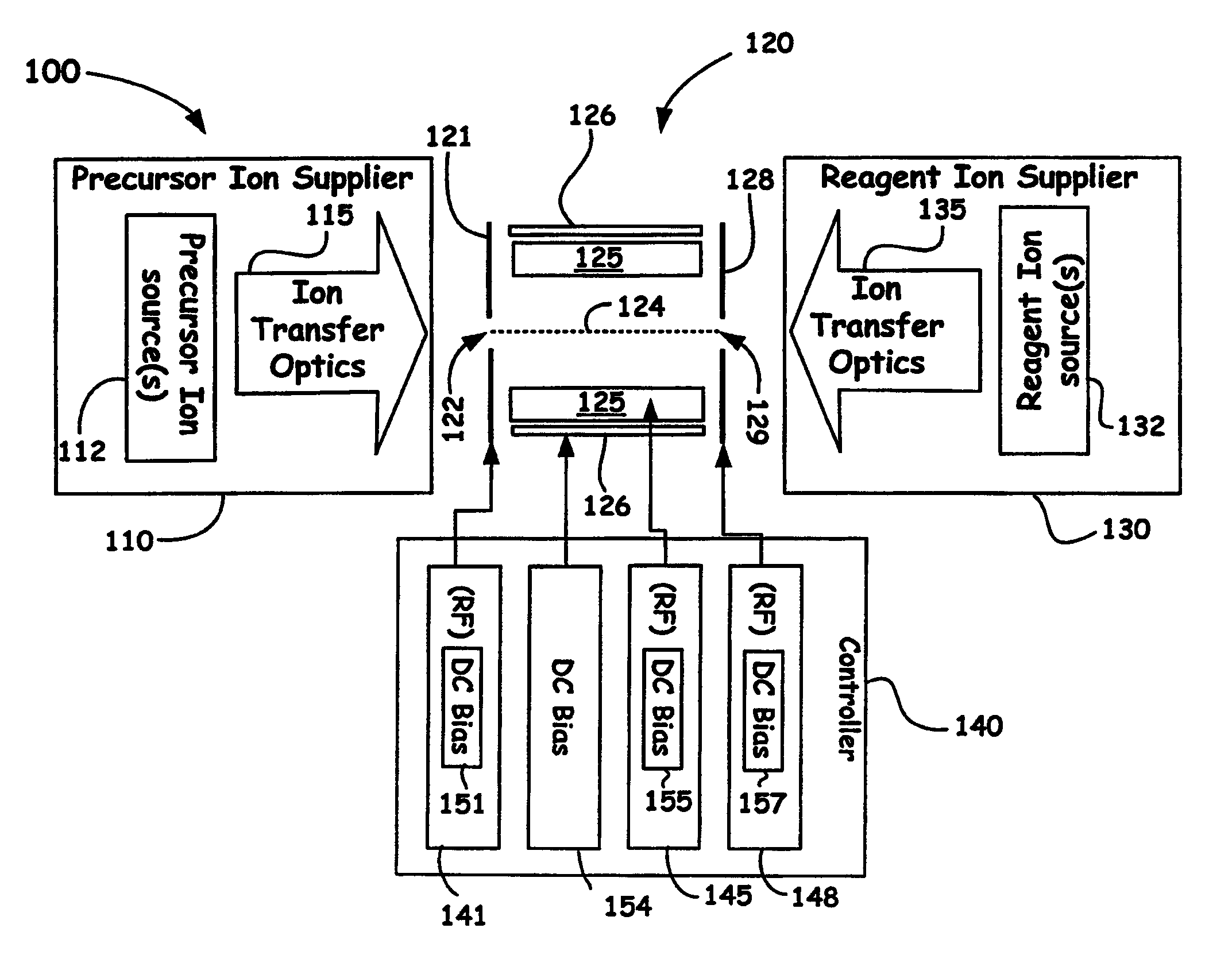
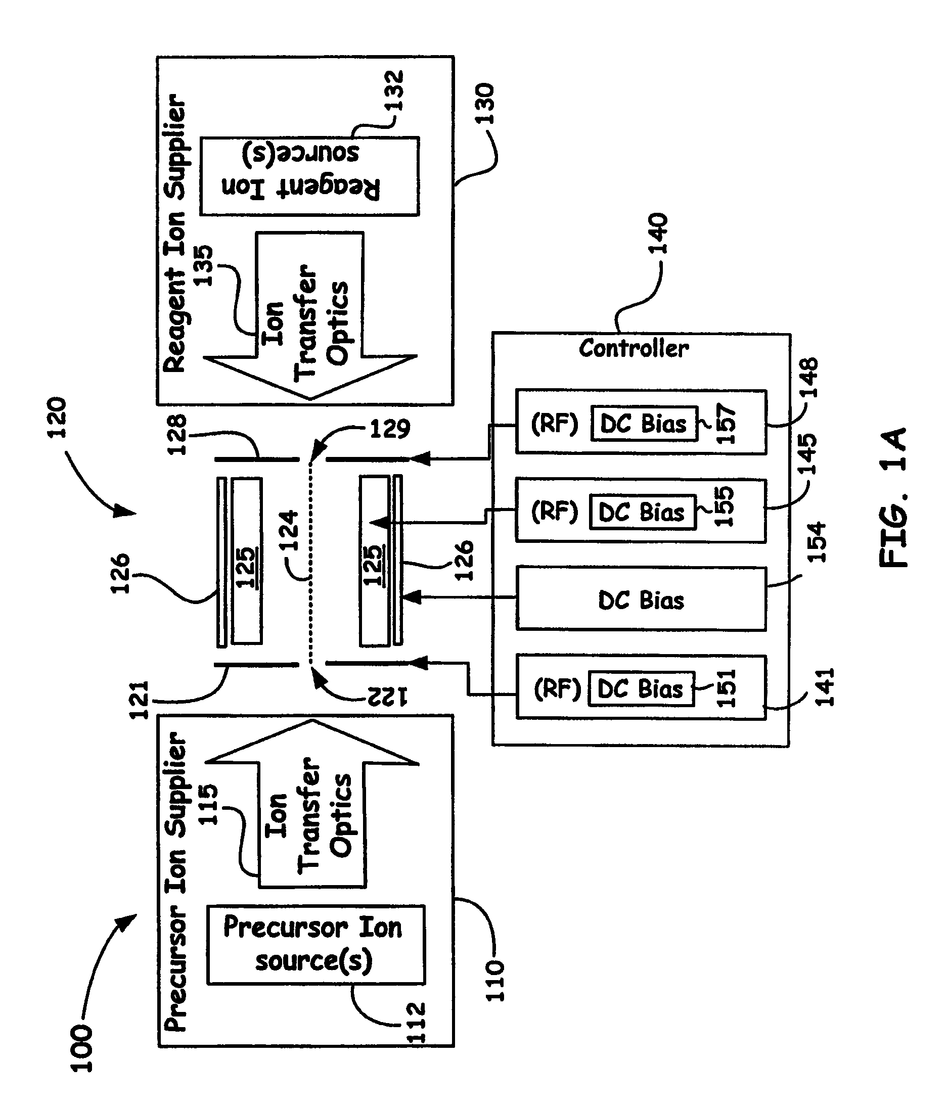
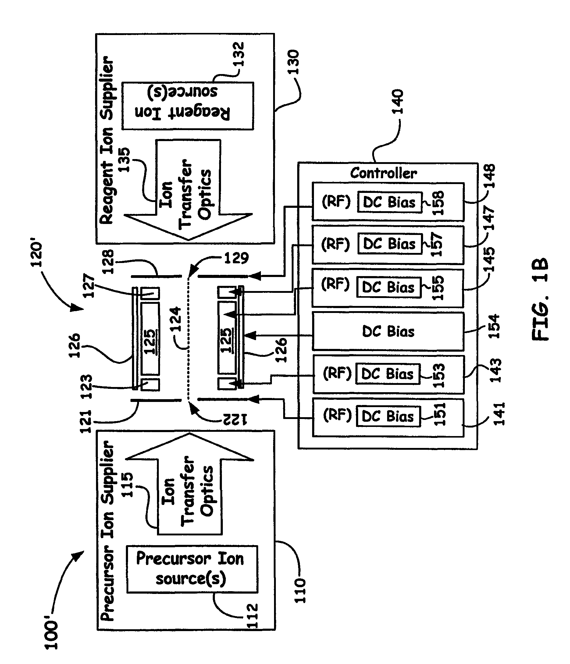
The present invention provides a method and system for fragmenting ions using a two-dimensional ion trap or multipole. The method involves introducing populations of ions of opposite polarity into an ion channel and providing a radially confining field and an additional static DC gradient along the axial length of the ion channel to confine the ions in an adjacent location with respect to each other. The ions are then arranged to interact with each other and produce desired product ions through diffusion, space charge, forced ion through, changing of the DC gradient, or time shifting of a customized plurality of ion storage volumes. The mass spectrometer system includes an ion supplier, a two-dimensional multipole, and a controller to confine the ions and produce desired product ions. The technical effects of the invention include improved accuracy and sensitivity in mass spectrometry analysis and efficient production of desired product ions.

Problems solved by technology

The analysis of organic compounds is especially challenging as such compounds cover a wide mass range from about 15 amu up to several hundred thousand amu, wherein the compounds themselves are often fragile and non-volatile.
However, while a (3D) quadrupole ion trap, e.g., Paul trap, forms a true 3D trapping potential it has only a limited space charge capacity.
However, ECD processes are difficult to carry out in an ion trap as the applied RF fields are not conducive for receiving low energy electrons.
Therefore, the technique remains exclusive to expensive MS instruments, such as, for example, FUR mass spectrometers.

Method used


Image

  • Dual ion trapping for ion/ion reactions in a linear RF multipole trap with an additional DC gradient
  • Dual ion trapping for ion/ion reactions in a linear RF multipole trap with an additional DC gradient
  • Dual ion trapping for ion/ion reactions in a linear RF multipole trap with an additional DC gradient

Examples


example applied

Voltages and Potentials

[0071]FIG. 2B, FIG. 2C, FIG. 2C′, and FIG. 2C″schematically illustrate a non-limiting example embodiment using example applied voltages and resultant potentials to illustrate a possible injection / reaction and subsequent ejection modes of operation of the present invention. As shown in FIG. 2B, an example 2D linear trap of the present invention includes a device having a length L of about 100 mm with r0 given as 4 mm (as also provided in Table 1 of FIG. 2B). Also shown are denoted applied potentials, as denoted by U1, U2, U3, and U4 at approximately the positions shown along the device. Table 1 gives the applied voltages along the length of the device to provide for such potentials. Below the example 2D linear trap as shown in FIG. 2B are three plots (shown not to scale) FIG. 2C, FIG. 2C′, and FIG. 2C″ of applied voltage profiles V1, V2, V3, and V4 that result in the applied potentials configured for injection (plot shown in FIG. 2C) and ejection (FIG. 2C′, and...


PUM


Abstract

A novel method and mass spectrometer apparatus is introduced to enable the simultaneous isolation of cations and anions (i.e., precursor and reagent ions) in a linear multipole ion trap via the application of an additional axial DC gradient in combination with coupled RF potential(s). Thus, the combination of the RF and DC voltages in such an arrangement forms a pseudopotential designed to provide for minima for the trapped positively and negatively charged particles that result in the overlap of the ion clouds so as to provide for beneficial ion / ion reactions.

Description

BACKGROUND OF THE INVENTION[0001]1. Field of the Invention[0002]The present invention relates to the field of mass spectrometry, and more particularly the present invention relates to 2D linear multipole traps configured to enable ion / ion reactions, such as, but not limited to electron transfer dissociation.[0003]2. Discussion of the Related Art[0004]Mass spectrometry is one of the most common and most important tools in chemical analysis and became a key technique in the discovery of the electron and the isotopes. The analysis of organic compounds is especially challenging as such compounds cover a wide mass range from about 15 amu up to several hundred thousand amu, wherein the compounds themselves are often fragile and non-volatile.[0005]In general, a mass spectrometer includes an ion source, a mass analyzer and some form of one or more detectors. As part of the function of the ion source, sample particles are ionized with techniques that can include chemical reactions, electrost...

Claims


Application Information

Patent Timeline
Patent Type & Authority Patents(United States)
IPC IPC(8): H01J49/42H01J49/06
CPCH01J49/0072H01J49/063H01J49/4295
Inventor NOLTING, DIRKGRIEP-RAMING, JENS
Owner THERMO FISHER SCI BREMEN
Learn More