Retaining structure

a technology of retaining structure and sliding mechanism, which is applied in the direction of washstands, dismountable cabinets, lighting support devices, etc., can solve the problems of difficult to fix or remove the sliding mechanism to or from the server without tools, such as screwdrivers

Active Publication Date: 2013-12-10
FULIAN PRECISION ELECTRONICS (TIANJIN) CO LTD
View PDF6 Cites 17 Cited by
  • Summary
  • Abstract
  • Description
  • Claims
  • Application Information

AI Technical Summary

Benefits of technology

[0004]A typical sliding mechanism of a server generally includes an inner rail, a middle rail, and an outer rail. The inner rail is mounted on the server, the outer rail is mounted to a support frame of the server, and the middle rail is mounted between the inner rail and the outer rail to extend the sliding distance of the sliding mechanism. However, in the conventional product configurations, the sliding mechanism is typically fixed to the server by some screws. Thus, it is difficult to fix or detach the sliding mechanism to or from the server without a tool, such as a screwdriver.

Problems solved by technology

Thus, it is difficult to fix or detach the sliding mechanism to or from the server without a tool, such as a screwdriver.

Method used


Image

  • Retaining structure
  • Retaining structure
  • Retaining structure

Examples


Embodiment Construction

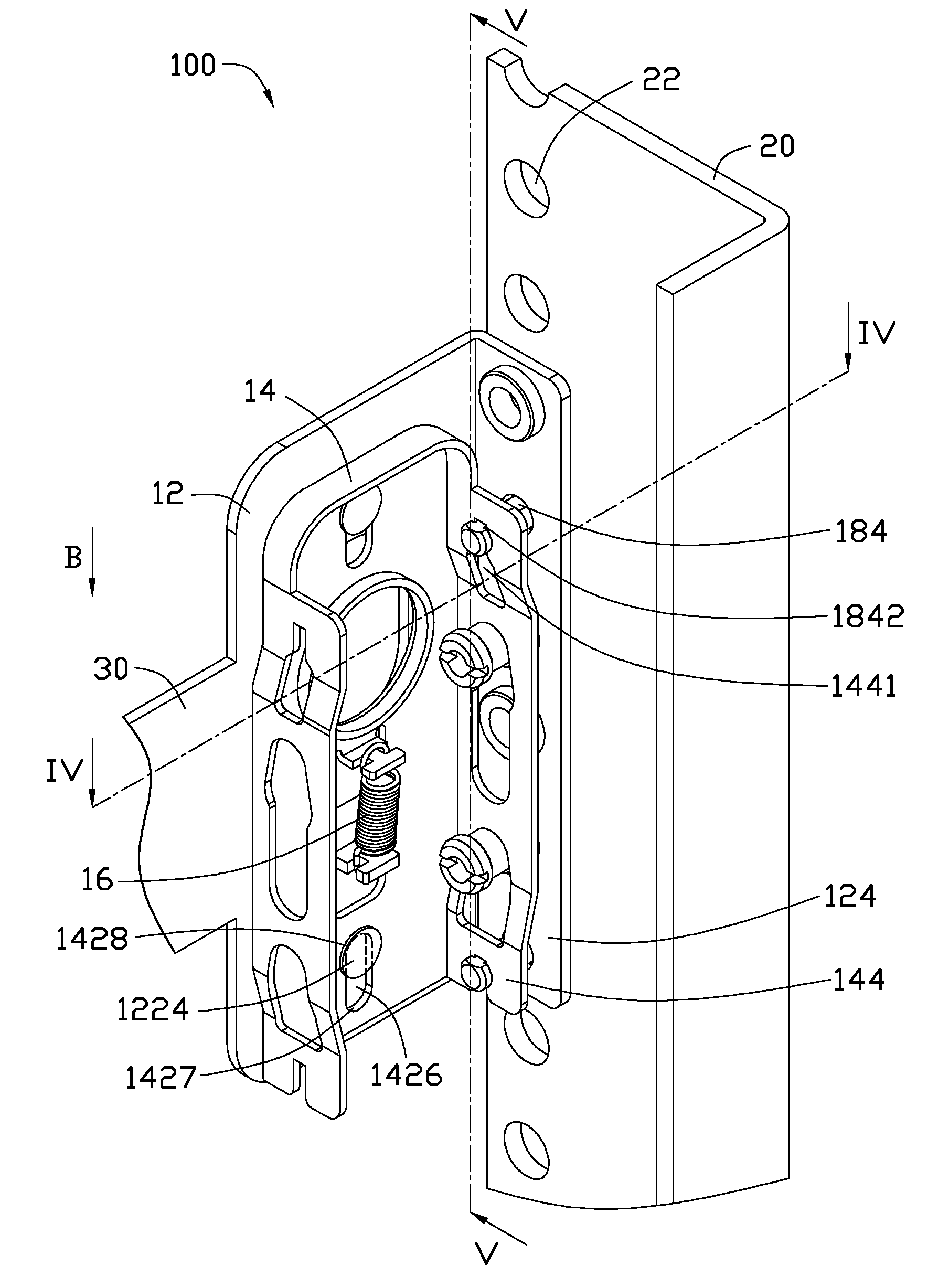
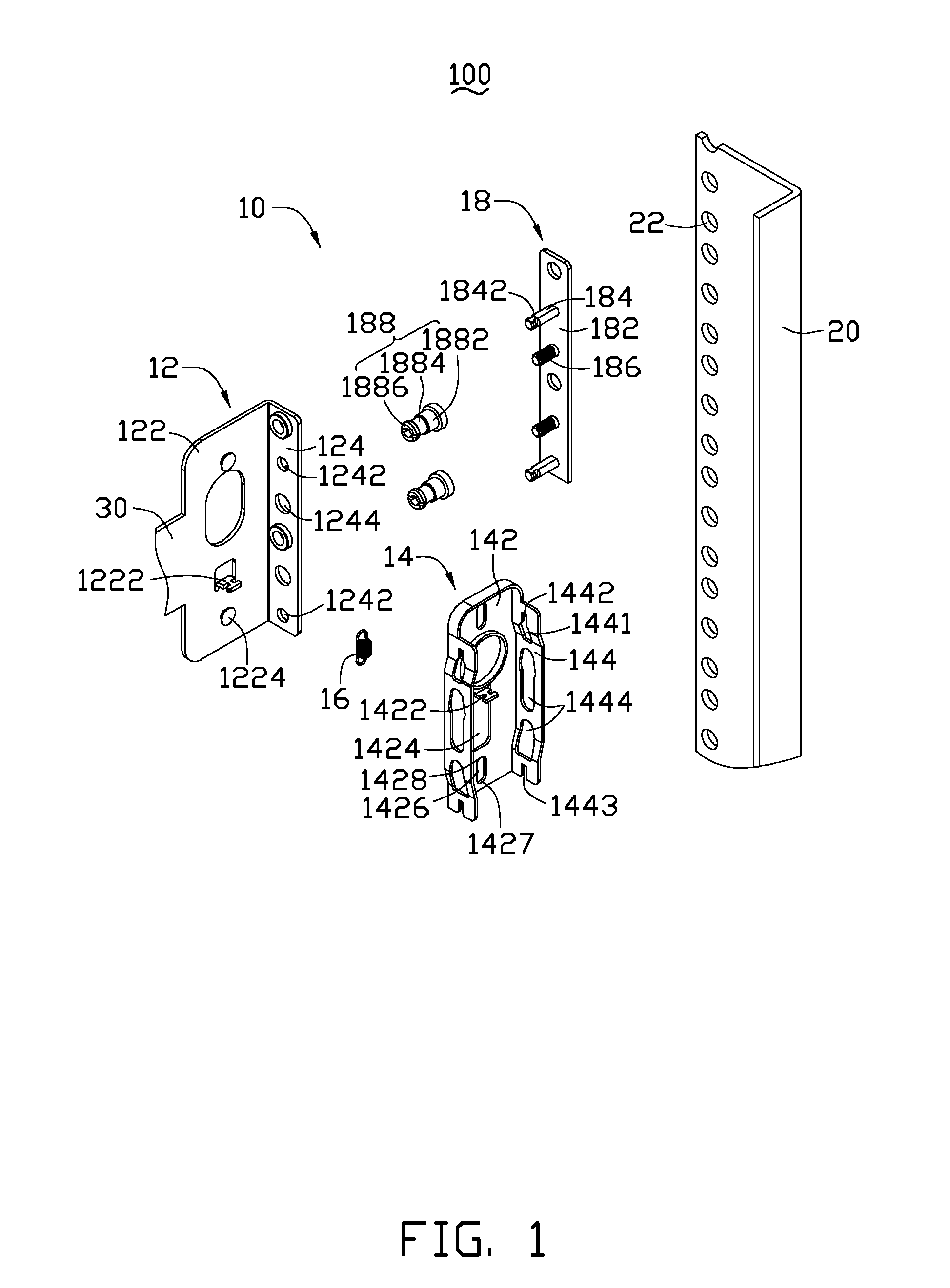
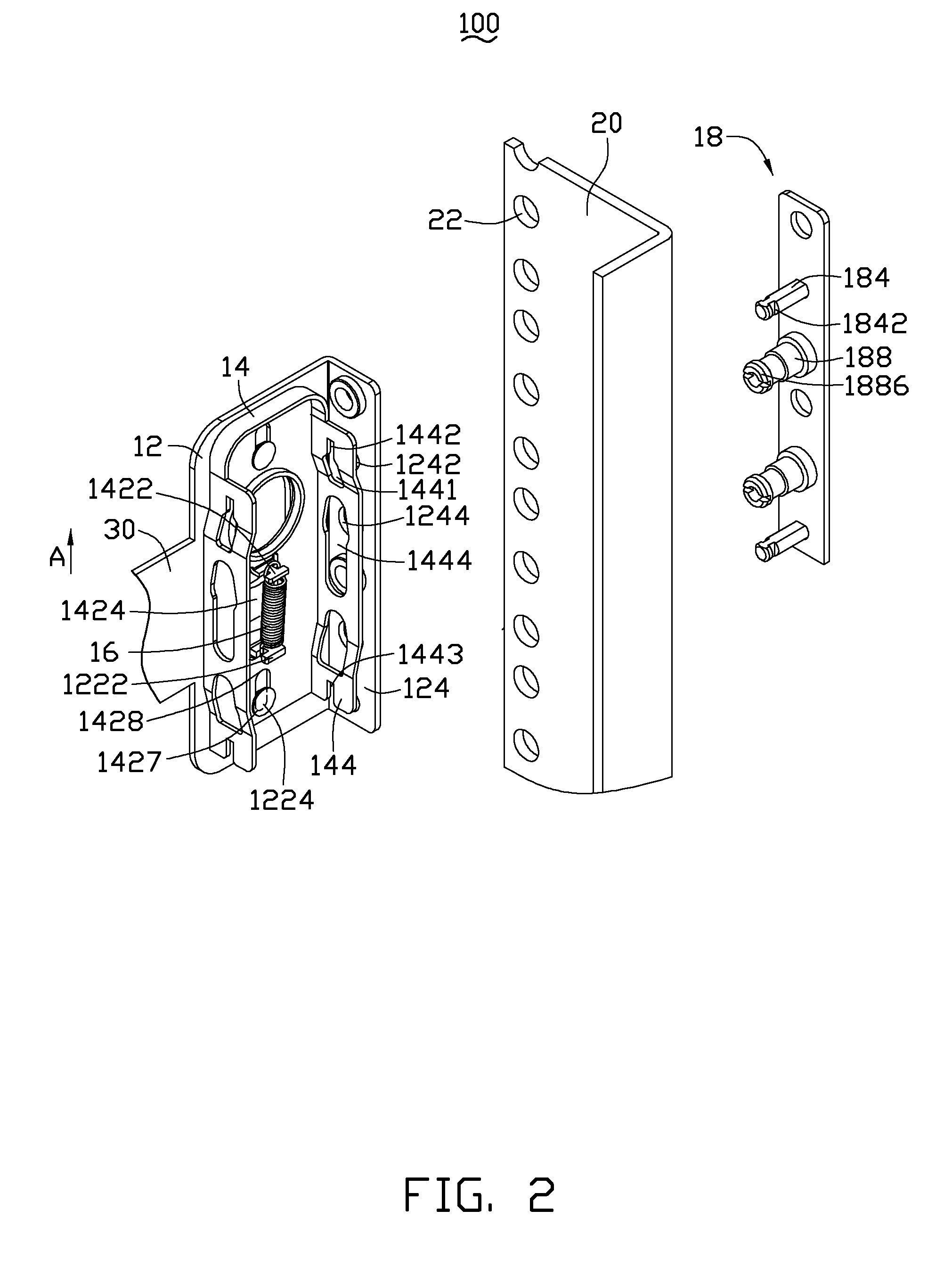
[0013]Referring to FIG. 1, an exemplary embodiment of a server 100 includes a bracket 20, a sliding rail 30 and a retaining structure 10. The retaining structure 10 retains the sliding rail 30 to the bracket 20.

[0014]The retaining structure 10 includes a retaining element 12, a securing element 14 slidably retained to the retaining element 12, a spring 16 connecting the retaining element 12 with the securing element 14 and a latching element 18 latching with the securing element 14. In this exemplary embodiment, the retaining element 12 is a portion of the sliding rail 30. In another exemplary embodiment, the retaining element 12 may be a separated element, and then retained to the sliding rail 30.

[0015]The retaining element 12 includes a retaining board 122 and a resisting board 124 bending from the retaining board 122. In this exemplary embodiment, the retaining board 122 is perpendicularly connected to the resisting board 124. The retaining board 122 protrudes a first retaining p...


PUM


Abstract

A retaining structure includes a bracket, a retaining element, a securing element, a spring and a latching element. The bracket defines a mounting hole. The retaining element defines an opening and having a pin. The securing element is slidably retained to the retaining element. The securing element defines a securing groove, a guiding groove and a sliding groove. The sliding groove has a first end and a second end. The spring connects the retaining element and the securing element. The latching element is latched with the securing element. The latching element including a latching board and a latching post protruding from the latching board.

Description

BACKGROUND[0001]1. Technical Field[0002]This disclosure relates to retaining structures, particularly to a retaining structure used in servers.[0003]2. Description of Related Art[0004]A typical sliding mechanism of a server generally includes an inner rail, a middle rail, and an outer rail. The inner rail is mounted on the server, the outer rail is mounted to a support frame of the server, and the middle rail is mounted between the inner rail and the outer rail to extend the sliding distance of the sliding mechanism. However, in the conventional product configurations, the sliding mechanism is typically fixed to the server by some screws. Thus, it is difficult to fix or detach the sliding mechanism to or from the server without a tool, such as a screwdriver.[0005]Therefore, there is a room for improvement in the art.BRIEF DESCRIPTION OF THE DRAWINGS[0006]Many aspects of the embodiments can be better understood with reference to the following drawings. The components in the drawings ...

Claims


Application Information

Patent Timeline
Patent Type & Authority Patents(United States)
IPC IPC(8): A47B96/00A47K1/00A47K5/00
CPCH05K7/1489
Inventor YU, MO-MINGHU, WEN-FENG
Owner FULIAN PRECISION ELECTRONICS (TIANJIN) CO LTD
Why Eureka
Try Eureka