Eureka AIR delivers breakthrough ideas for toughest innovation challenges, trusted by R&D personnel around the world.

Systems and methods for manufacturing quantum dot-doped polymer microbeads

a polymer microbead and quantum dot technology, applied in the field of detection polymer microbeads, can solve the problems of difficult control of qd density inside the beads, difficulty in controlling the qd density of beads, and/or the diffusion of qds out of the polymer matrices, and achieve the effect of reducing the cross-sectional profile of the polymer stream

Inactive Publication Date: 2013-12-03
FIO CORP
View PDF204 Cites 1 Cited by
  • Summary
  • Abstract
  • Description
  • Claims
  • Application Information

AI Technical Summary

Benefits of technology

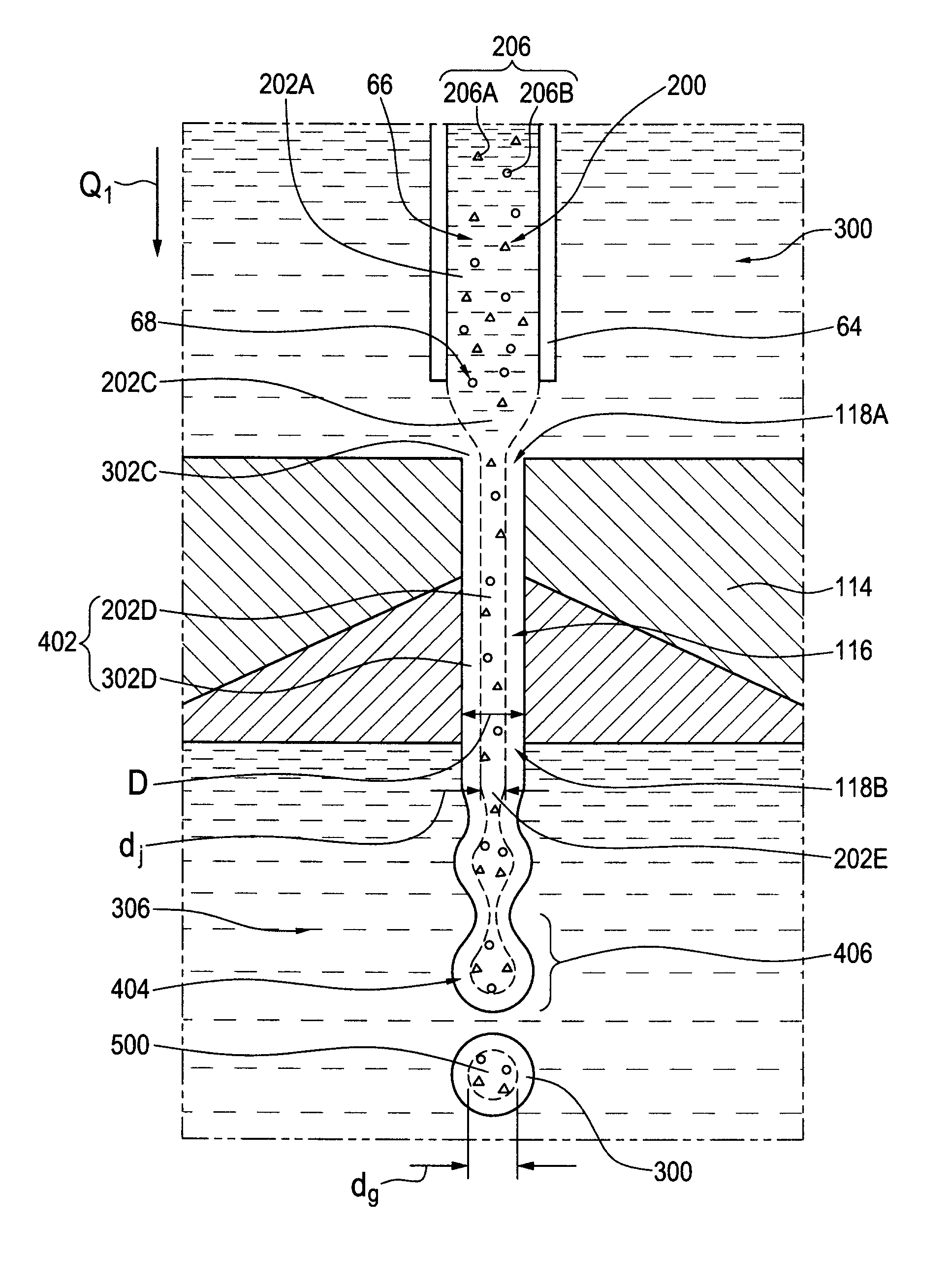
[0068]According to an aspect of one preferred embodiment of the invention, the second polymer nozzle may preferably, but need not necessarily, be adapted to operatively further reduce the cross-sectional profile of the polymer stream during passage therethrough.
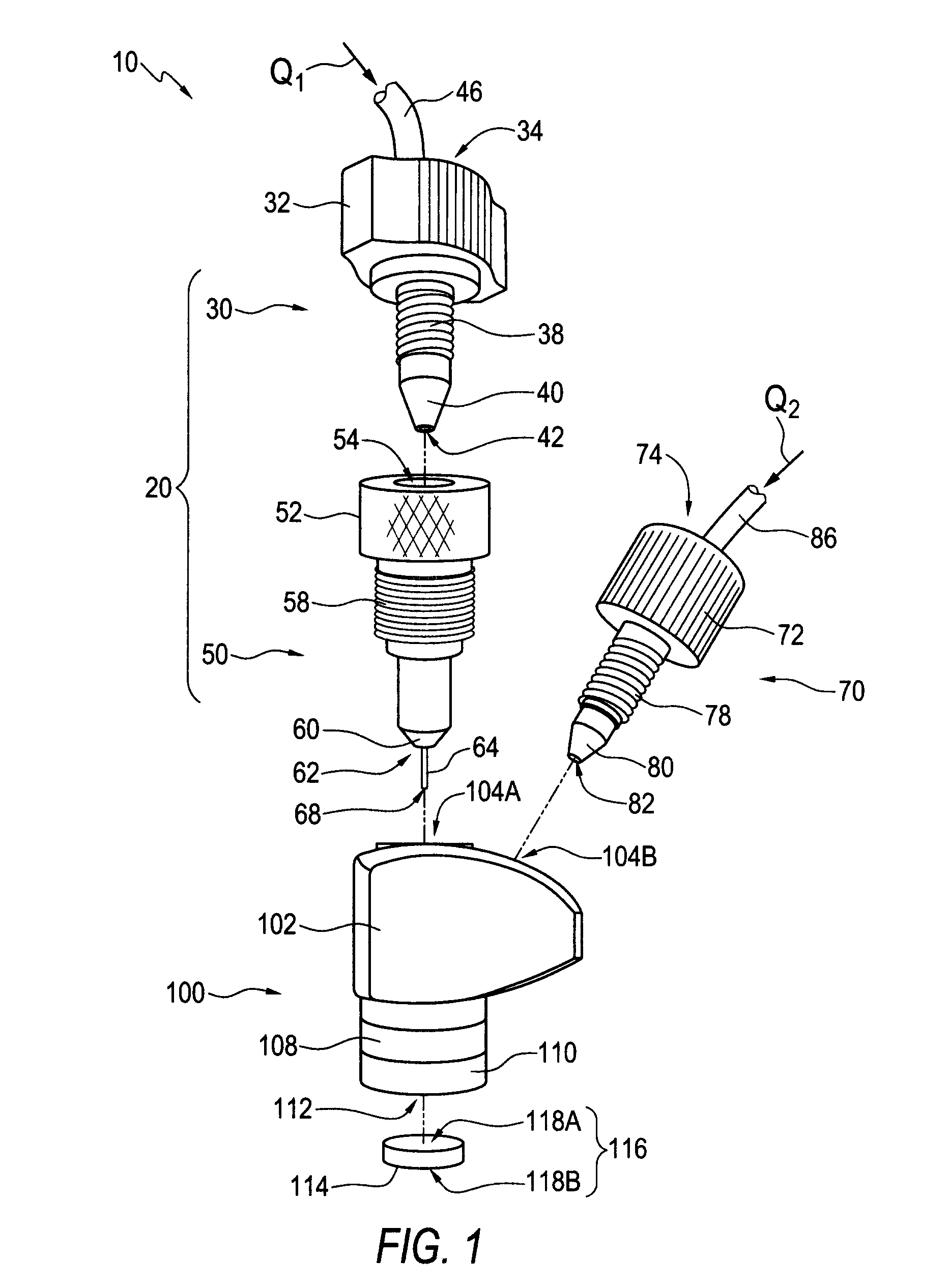
[0070]According to an aspect of one preferred embodiment of the invention, the flow focusing apparatus may preferably, but need not necessarily, also include a focusing fluid supply nozzle. The focusing fluid supply nozzle may preferably, but need not necessarily, have an entry portion shaped to define an entry opening, an exit portion shaped to define a tip aperture, and / or a neck portion shaped to define an internal channel running between the entry opening of the focusing fluid supply nozzle and the tip aperture of the focusing fluid supply nozzle. A focusing stream of the focusing fluid may preferably, but need not necessarily, operatively flow into the entry opening of the focusing fluid supply nozzle, through the internal channel of the focusing fluid supply nozzle, and / or out from the tip aperture of the focusing fluid supply nozzle towards the chamber. The focusing fluid supply nozzle may preferably, but need not necessarily, be adapted to operatively reduce a cross-sectional profile of the focusing stream during passage therethrough.

Problems solved by technology

Unfortunately, however, there has not yet been developed any simple one-step method for the large scale manufacture of labeled and / or marked polymer microbeads having a uniform shape, homogenous distribution, and / or controlled fluorescent properties.
The size-dependent properties of QDs which might make their use preferable in comparison to dyes may also, however, be what makes them more difficult to manipulate.
The incorporation of QDs into polymer microbeads, as an alternative to organic dyes, may create additional manufacturing challenges and / or may increase the need for high quality, uniform and / or stable polymer beads.
Major drawbacks of this prior art technique may have included difficulties in controlling the QD density inside the beads and / or diffusion of QDs out from the polymer matrices.
Problems encountered with this type of approach may have included poor control of bead diameter and / or lack of monodispersity.
Heretofore, however, it has not been readily apparent to those of ordinary skill in the art how one might adapt such flow focusing techniques to make polymer microbeads incorporating nanoparticles (e.g., in particular, QDs and / or magnetic nanoparticles), inter alia, in a one-step method.
A number of problems have instead presented themselves in this regard.
Specifically, the flow focusing approach has thus far failed to account for certain technical considerations required to incorporate QDs into polymer microbeads—e.g., QD solubility and stability in the solvent of choice, polymer solubility and compatibility with the QD / solvent system.
One particularly problematic shortcoming of existing flow focusing technologies is their general failure to account for how QD-doped polymer microbeads might be designed for subsequent conjugation to BRMs.
Prior art polymers with carboxylic acids in their repeating units may, however, have presented a solubility challenge, since they may have been too hydrophilic to dissolve in solvents that are compatible with QDs.

Method used


Image

  • Systems and methods for manufacturing quantum dot-doped polymer microbeads
  • Systems and methods for manufacturing quantum dot-doped polymer microbeads
  • Systems and methods for manufacturing quantum dot-doped polymer microbeads

Examples


example 1

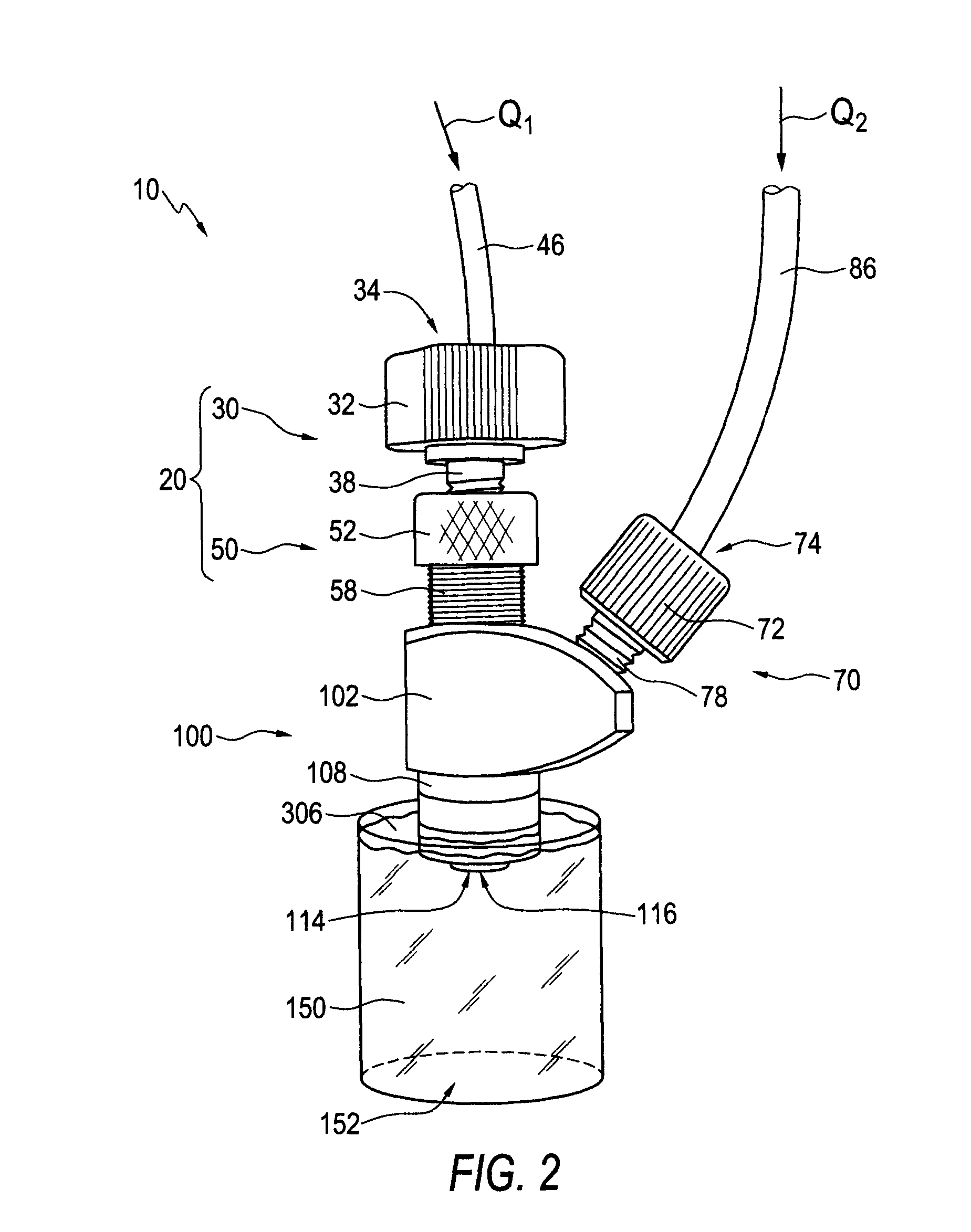
[0176]A barcode was designed by mixing QD / chloroform solutions of different colors in appropriate ratios in order to generate the desired barcode emission spectrum of 520 nm, 580 nm and 630 nm with a 1:2:3 ratio. Into the chloroform mixture, commercial poly(styrene-co-maleic anhydride), cumene terminated powder (from Aldrich) (or derivatives) was dissolved to create a 4% polymer solution. The resulting solution was then introduced into a commercial nozzle (Avant-1 from Ingeniatrics) using a syringe pump (SP100I from World Precision Instruments) at a rate of 1 mL / h along with water as a focusing fluid using a digital gear pump (Cole Parmer Instrument Company) at a rate of 180 mL / h. During the reaction, the nozzle was immersed into a water solution under stirring. Beads were hardened by overnight stirring and collected by centrifugation.

example 2

[0177]In this example, the following QD-based barcode was used: 555 nm, 580 nm, 605 nm with a respective intensity ratio of 1:2:1. The solution was made using the same protocol as Example 1 using poly(styrene-co-maleic anhydride).

example 3

[0178]The same protocol was used as in Example 1, however, the QDs were replaced by magnetite nanoparticles (from Ferrotec Corporation) dissolved into chloroform. This example resulted in paramagnetic microbeads that are attracted to a magnet and lose their magnetism upon removal of the magnetic field.


PUM

PropertyMeasurementUnit
diameteraaaaaaaaaa
diameteraaaaaaaaaa
flow rateaaaaaaaaaa

Abstract

In a method and system for forming microbeads, a polymer solution includes particles and a polymer dissolved in a solvent. A stream of the polymer solution flows into a chamber. A focusing fluid contacts and focuses the polymer stream in the chamber. The focusing fluid and the focused polymer stream flow, as a single flow stream, out from the chamber. Pendant droplets detach from a leading end of the single flow stream to form the microbeads. The focusing fluid reacts with the polymer solution to form functional groups at a surface of the microbeads for binding with biorecognition molecules. In the system, a flow focusing apparatus includes a flow focusing body shaped to define the chamber. Microbeads formed according to the methods and systems are also disclosed.

Description

FIELD OF THE INVENTION[0001]The present invention relates generally to the field of detectable polymer microbeads for use as diagnostic tools, and more particularly, to systems and methods for manufacturing polymer microbeads doped with identifiable particles, preferably nanoparticles and more preferably quantum dots, using directed and controlled flows of fluids.BACKGROUND OF THE INVENTION[0002]Detection and / or characterization of diseases and / or ailments in a host can be a complex process that may typically involve the identification of one or more causative agents (e.g., pathogens). There may also frequently have existed a need and / or desire to detect, characterize and / or identify one or more poisons, toxins, and / or genetic expression factors.[0003]Substantially spherical particles (also known as microspheres or microbeads) bearing identifiable labels and / or markings—colloquially called “barcoded microbeads”—may have been used in parallel multiplexed analyses and / or in the identi...

Claims


Application Information

Patent Timeline
Patent Type & Authority Patents(United States)
IPC IPC(8): B05D1/02B05B1/34B05B7/26B05D1/42B05D1/34B05D1/26B32B5/16
CPCC40B20/04B01J2219/005B01J2219/00551B01J2219/00576C08L25/14C08L35/06Y10T428/2982
Inventor FOURNIER-BIDOZ, SEBASTIENCHAN, WARREN CHE WOR
Owner FIO CORP
Why Eureka
Eureka Blog
Learn More