
Microvalve controlled precision fluid dispensing apparatus with a self-purging feature and method for use

a technology of precision fluid dispensing and micro-valve, which is applied in the direction of volume metering, laboratory glassware, instruments, etc., can solve the problems of difficult control, difficult control, and high cost of oligonucleotide probes, so as to achieve efficient purging of residual samples, reduce sample wastage, and save costs

Active Publication Date: 2013-12-03
CAPITALBIO CORP +1
View PDF10 Cites 1 Cited by
  • Summary
  • Abstract
  • Description
  • Claims
  • Application Information

AI Technical Summary

Benefits of technology

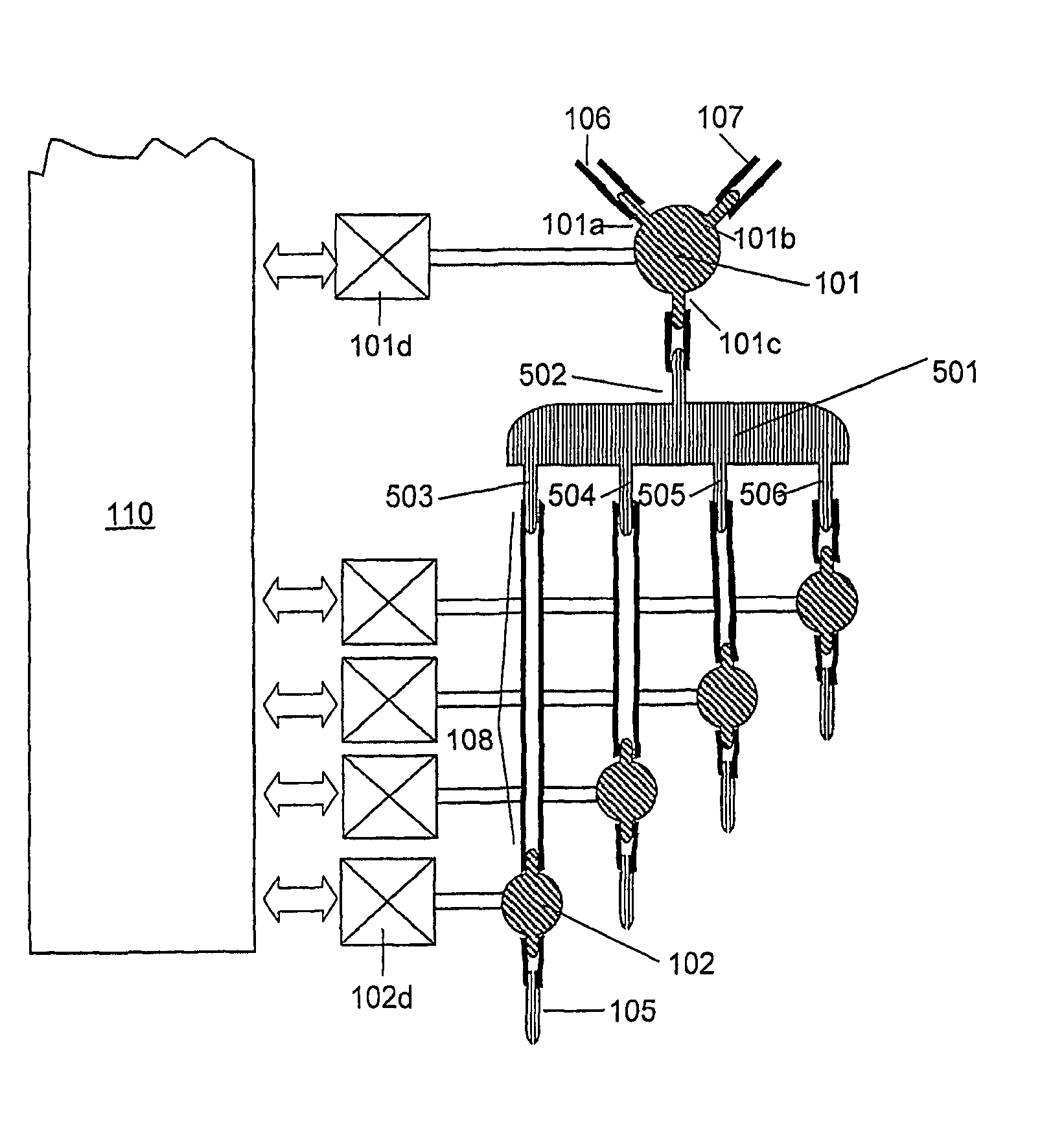
[0009]Embodiments of the present invention provide apparatus and methods for the precise, repeatable dispensing of small sample volume drops, especially as related to the fabrication of microarrays for biological and / or chemical testing. A pressure tuning module (for example: a syringe pump, adjustable bellows, or similar mechanism) meters sample volumes for aspiration and adjusts the pressure applied on the sample to be dispensed in conjunction with a microvalve that precisely controls the volume of the fluid dispensed. A pressure source, can be switched in line to efficiently purge the apparatus of residual sample. A working fluid can be optionally aspirated into the system, prior to aspirating the sample fluid, in order to minimize sample wastage.

Problems solved by technology

Typically more than 100,000 different samples can be created on a 1.3 cm×1.3 cm substrate surface, but the technique is expensive and limited to oligonucleotide probes of twenty to thirty base sequences because the oligonucleotide probes are usually synthesized in situ on the substrate from nucleotides in solution.
Split pin contact printing is one of the most popular current technologies for fabricating microarrays, however the sample volume printed for each spot depends on the physical dimensions of the split end of the pin which are difficult to control.
Consequently the accuracy and reproducibility of printed sample fluid volumes are difficult to control at the nanoliter to microliter quantities typically dispensed.
Piezoelectric jet and thermal bubble jet sample fluid applicators, derived from inkjet printer technologies, have been adapted to biochip microarray manufacture, however equipment costs tend to be high.
Such wastage of biological sample fluid can be very costly.
Also, the BioJet Plus™ series dispensers can take a long time to purge residual sample fluid when changing samples because it is difficult to expel all residual droplets and bubbles using the syringe pump before aspirating a new sample.

Method used


Image

  • Microvalve controlled precision fluid dispensing apparatus with a self-purging feature and method for use
  • Microvalve controlled precision fluid dispensing apparatus with a self-purging feature and method for use
  • Microvalve controlled precision fluid dispensing apparatus with a self-purging feature and method for use

Examples


Embodiment Construction

[0015]Unless defined otherwise, all technical and scientific terms used herein have the same meaning as is commonly understood by one of ordinary skill in the art to which this invention belongs. All patents, applications, published applications and other publications referred to herein are incorporated by reference in their entirety. If a definition set forth in this section is contrary to or otherwise inconsistent with a definition set forth in applications, published applications and other publications that are herein incorporated by reference, the definition set forth in this section prevails over the definition that is incorporated herein by reference.

[0016]As used herein, “a” or “an” means “at least one” or “one or more.”

[0017]FIG. 1 is a schematic diagram of an embodiment of the present invention. Nozzle 105 is used to pick up, hold, and dispense a sample fluid 110c. Nozzle 105 is connected to port 102c of microvalve 102 via coupling 109. Coupling 109 can be tubing or screw a...


PUM


Abstract

An apparatus and methods for the precise, repeatable dispensing of small, sample fluid volumes, especially as related to the printing of microarrays for biological and / or chemical testing. A pressure tuning module meters fluid volumes for aspiration and dispensation and builds pressure for fluid dispensation, in conjunction with a microvalve that precisely controls the volume of the fluid dispensed under the built pressure. A pressure source can be switched in line to efficiently purge the apparatus of residual sample fluid. A working fluid can be optionally aspirated into the system, prior to aspirating the sample fluid, in order to maximize sample fluid recovery.

Description

CROSS-REFERENCE TO RELATED APPLICATIONS[0001]This application is the national phase of PCT application PCT / CN2006 / 000055 having an international filing date of Jan. 13, 2006, which claims priority from China application number 200510102436.2 filed Sep. 9, 2005. The contents of these documents are incorporated herein by reference.TECHNICAL FIELD[0002]The present invention relates to an apparatus and method for repeatably dispensing small, precise volumes of fluids with little wastage of sample. In particular, the present invention may be applied to the fabrication of microarrays for biological and chemical testing.BACKGROUND ART[0003]Biochip microarrays can be two-dimensional arrays of reference biological materials on substrates such as glass membranes or similar materials. Microarrays are fabricated by printing small volumes of solution containing the reference biological material on a substrate. Types of technologies for fabricating biochip microarrays include photolithography, co...

Claims


Application Information

Patent Timeline
Patent Type & Authority Patents(United States)
IPC IPC(8): B01L3/00
CPCB01L3/0265B41J2/175B41J2/17596B01J2219/0036B01J2219/00364B01L2400/0478Y10T436/2575G01N2035/00247G01N2035/1041B01L2400/0622
Inventor WANG, DONGZOU, KUNCHENG, JING
Owner CAPITALBIO CORP
Learn More