Floating dock mover

a dock mover and floating technology, applied in the direction of special-purpose vessels, hoisting equipment, vessel construction, etc., can solve the problems of no access to the dock, inaccessible and therefore unusable, and time-consuming

Active Publication Date: 2013-12-03
RAMEY LESTER L +1
View PDF20 Cites 3 Cited by
  • Summary
  • Abstract
  • Description
  • Claims
  • Application Information

AI Technical Summary

Problems solved by technology

If the dock isn't relocated, it can become inaccessible and therefore unusable.
When it becomes isolated, there is no access to the dock without going through water.
But they are found to be time consuming and difficult to operate.
This system requires a lot of manual effort to get the dock moving toward shore and to keep it moving in a desired perpendicular path to shoreline.
This manual process of moving the dock assembly is difficult and typically requires a plurality of people.
Windy conditions can make it near impossible to move it without additional manual help.
Because it utilizes a permanent anchor to the bottom of the body of water, the stairway would not be permitted on many lakes and reservoirs.
Furthermore, this patent would not be practical if the beach angle and angle of dirt just below the shoreline is a low angle.
In addition, the guide rails are not practical for lakes or bodies of water that have a low angle of beach because they would have to be long in length.
This would not be practical.
U.S. Pat. No. 3,276,211 to Drake (1966) does not allow for horizontal relocation of the Dock.
This would not be permitted on many lakes and reservoirs that require only floating docks.
The anchor system is manually positioned 59 and 60 stake members and therefore not practical for relocating a dock due to changing water levels.
Additionally, it is not tethered to the shore with cables or the like and in windy conditions can easily get turned and off perpendicular with the shoreline.
This will disturb the land below the water and eventually wear a pathway groove in the bottom surface 30.
This would be impractical if the traveling distance was more than a few feet in either direction, or a steep direction.
Manually inputting additional spring pressure utilizing hand crank 20 would be difficult to provide enough spring force to allow the boat dock to move up a steep beach.

Method used


Image

  • Floating dock mover
  • Floating dock mover
  • Floating dock mover

Examples


embodiment invention

Operation of Preferred-Embodiment Invention

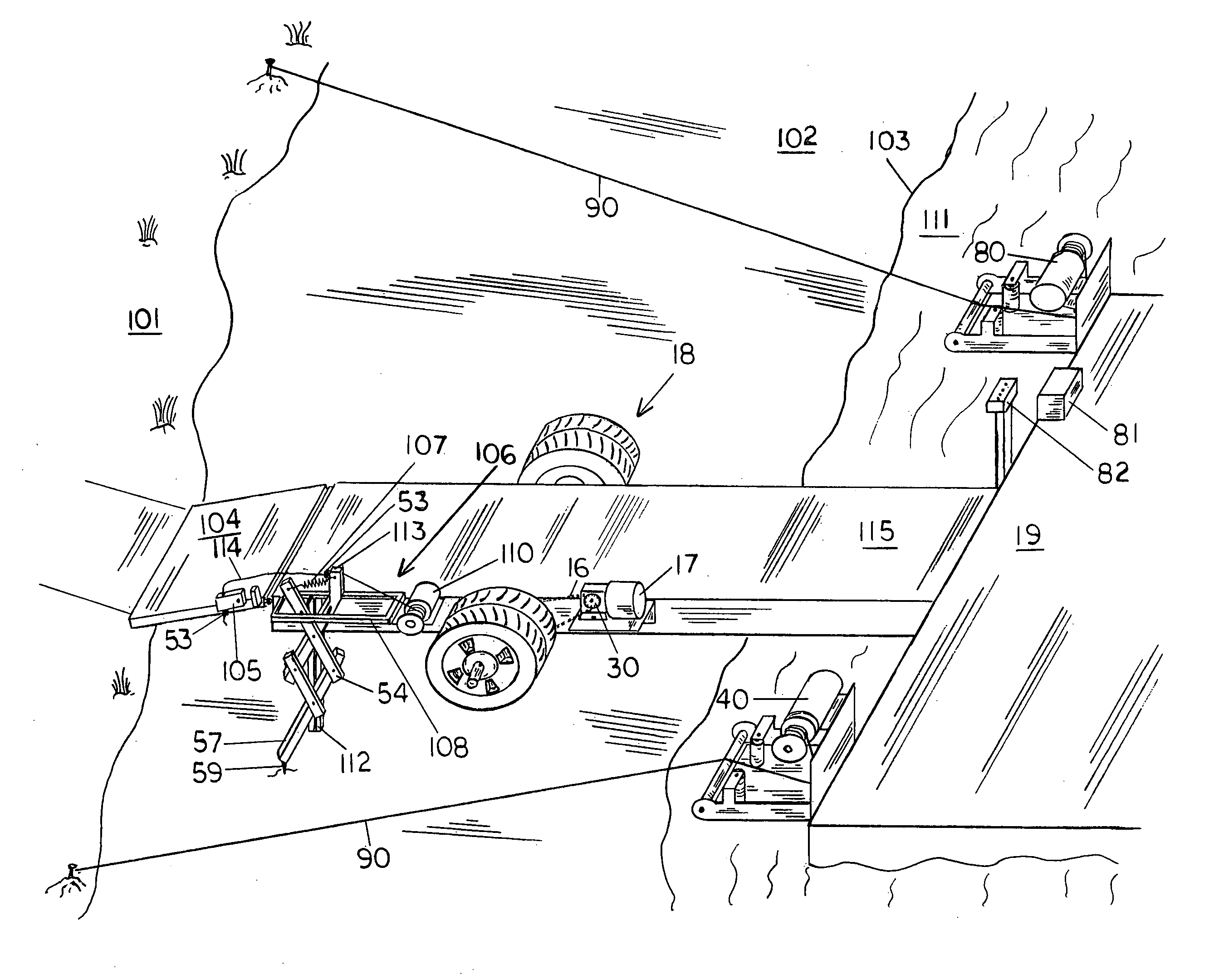
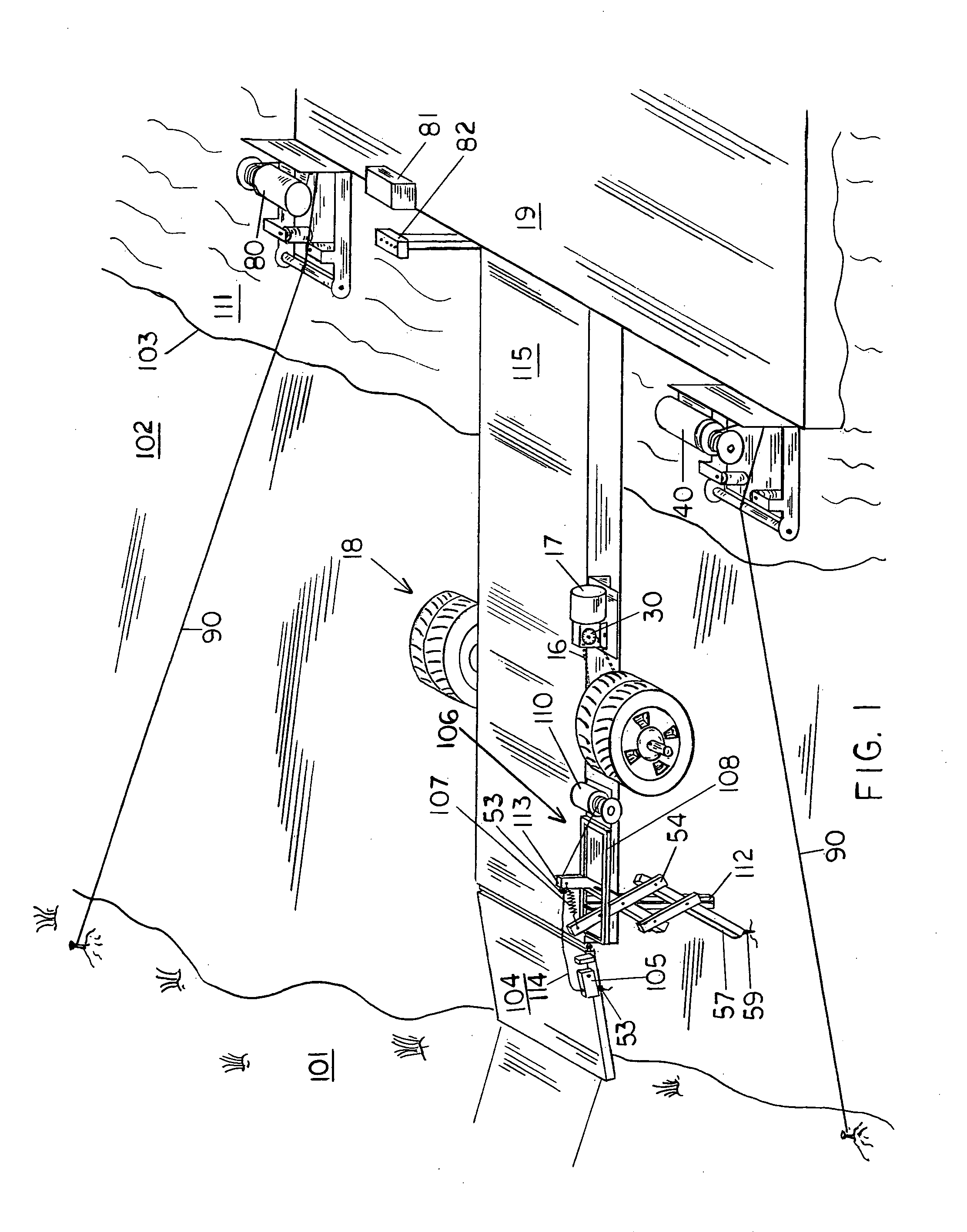
[0060]In operation, the preferred embodiment invention will function as follows: To relocate the dock mover of this invention toward the main body of water, operator control center 82 shown in FIG. 1 is accessed by an operator and switch 93B shown in FIG. 10 is activated in a back position thereby causing FIG. 1 anchor / ramp winch 110 to take-in winch cable 114, thereby causing pivot arm 105 to rise and stop rotation against stop 109 shown in FIG. 9. Continued motion of anchor / ramp winch 110 will cause FIG. 1 walkway ramp 104 to rise.

[0061]FIG. 1 and FIG. 8 reflects that with the same continued anchor / ramp winch 110 rotation as noted previously, primary winch anchor arm 113 will move toward anchor / ramp winch 110. As primary winch anchor arm 113 moves closer to anchor / ramp winch 110, guide bolts and nuts 56 shown in FIG. 8 slide upward within vertical guide 112, thereby causing anchor cross arm 54 to move away from primary winch anchor arm 11...


PUM


Abstract

A floating dock mover that utilizes electrically powered devices to aid in relocating a floating dock whenever water levels change in a lake or reservoir. Electrical powered winching mechanisms are used to adjust cables lengths to maintain a position, or aid to obtain a new position of the dock in relation to the shoreline.Additionally, a motorized speed reducer is used to turn the wheels on the dock walkway, which moves the walkway and dock away from, or toward the shore. By electrically powering winch cable lengths, plus electrically powering the walkway wheels, the dock can be relocated horizontally and vertically and maintain a relative desired position in relation to a moving shoreline. An additional electrically motorized unit is used to operate an anchor which aids in maintaining a dock in a desired position.

Description

[0001]This application claims the benefit of Provisional Patent Application Ser. No. 61 / 461,303, filed Jan. 18, 2011 by the present inventors, which is incorporated by reference.REFERENCES CITEDPrior Art—U.S. Patent Documents[0002]3,050,947Aug. 28, 1962J. E. Burton3,088,287May 7, 1963 V. C. Berry3,276,211Oct. 4, 1966T. R. Drake3,683,838Aug. 15, 1972B. L. Godbersen5,238,324Aug. 24, 1993Dettling, Jr.5,282,435Feb. 1, 1994H. S. Chapman6,295,944Oct. 2, 2001J. Timothy LovettBACKGROUND[0003]1. Field of Invention[0004]This invention relates to a new and useful method to relocate a floating dock in relation to a shoreline that moves due to the rise and fall of reservoir and lake water levels.[0005]2. Discussion of Prior Art[0006]It is a common necessity of floating dock owners, and property caretakers of lake front property to periodically relocate a dock in relation to the shoreline. On many lakes and reservoirs in the United States water level changes frequently. With water level changes, ...

Claims


Application Information

Patent Timeline
Patent Type & Authority Patents(United States)
IPC IPC(8): B60P3/10
CPCB63B21/16B63B27/14B63B21/26B63B35/34B63H19/08B63B35/00B63B27/143E01D15/24
Inventor RAMEY, LESTER L.DAWKINS, RICHARD H.
Owner RAMEY LESTER L
Why Eureka
Try Eureka