
Lighting system, dimming control apparatus and dimming control method

a dimming control and dimming control technology, applied in the direction of instruments, light sources, electroluminescent light sources, etc., can solve the problems of increased deployment costs, limited number of addressable units, and increased costs inevitably, so as to facilitate the wide use of led lighting systems, simplify the implementation of the circuit of the dimming control apparatus, and reduce the cost of lighting system deploymen

Active Publication Date: 2013-11-19
IND TECH RES INST
View PDF41 Cites 17 Cited by
  • Summary
  • Abstract
  • Description
  • Claims
  • Application Information

AI Technical Summary

Benefits of technology

[0007]The disclosure is directed to a dimming control apparatus and a method thereof. By decoding a dimming command into a plurality of sub-dimming commands, addressable dimming control can be performed on different modularized lamp modules, individually. Therefore, the complexity in the implementation of the circuit of the dimming control apparatus can be simplified, and addressable dimming control can be performed on multiple LED modules individually. The cost of the lighting system deployment can be reduced so as to facilitate the wider use of the LED lighting systems.

Problems solved by technology

However, the development and popularity of LED technologies encounter bottlenecks and they should be broken through with respect to different aspects, rather than the design aspect only.
For indoor lighting applications that require dimming function to control each unit, the cost will be increased inevitably.
The disadvantage of the general lighting control system, such as digital addressable lighting interface (DALI) or digital multiplex interface (DMX), is that the number of addressable units is limited.
For providing dimming control for individual LED module, an LED lighting system including a number of LED fixtures must employ a considerable number of digital dimming systems, resulting in a higher cost for deployment.
Such a high cost would affect the popularity of the LED lighting system with individual dimming control.

Method used


Image

  • Lighting system, dimming control apparatus and dimming control method
  • Lighting system, dimming control apparatus and dimming control method
  • Lighting system, dimming control apparatus and dimming control method

Examples


first embodiment

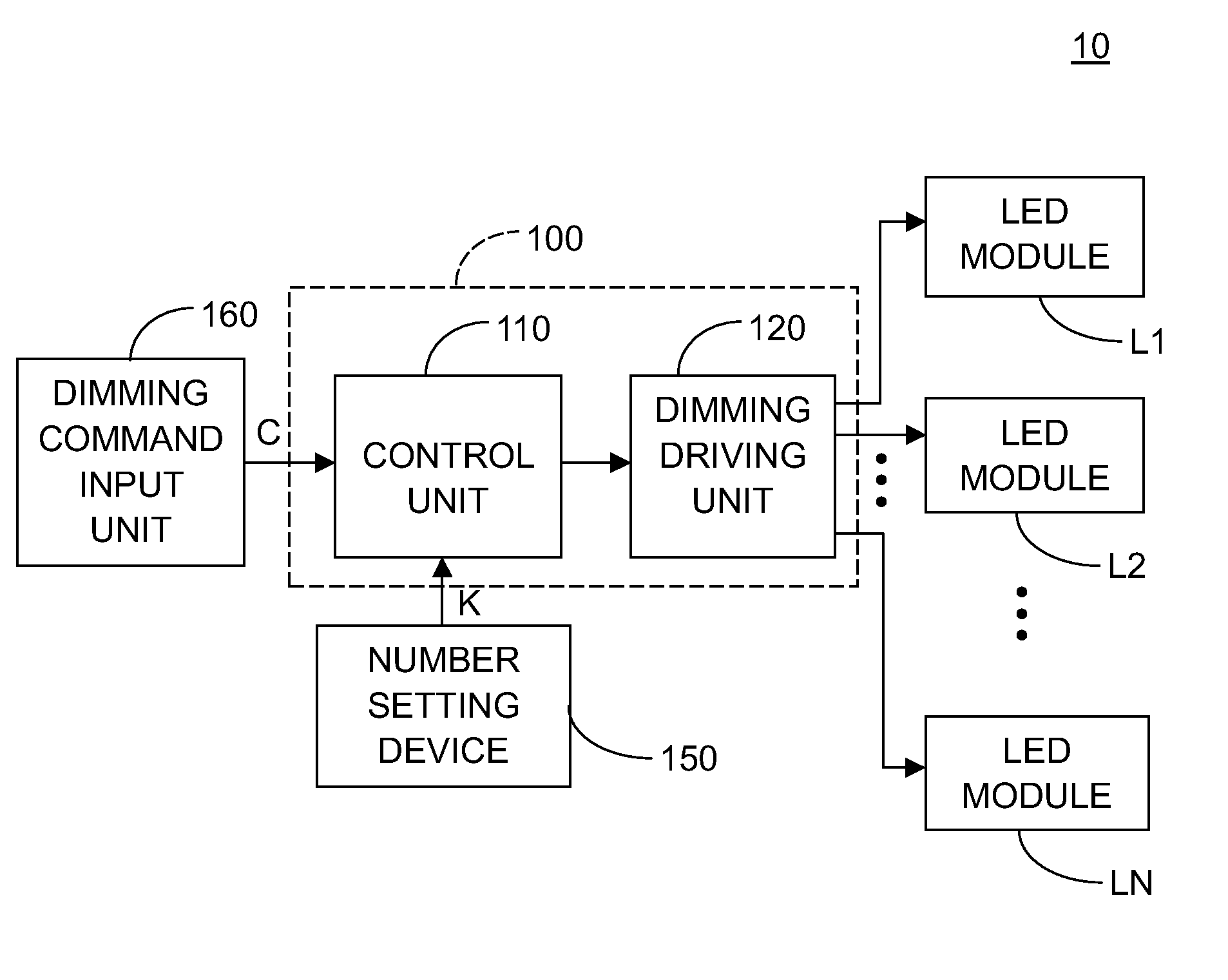
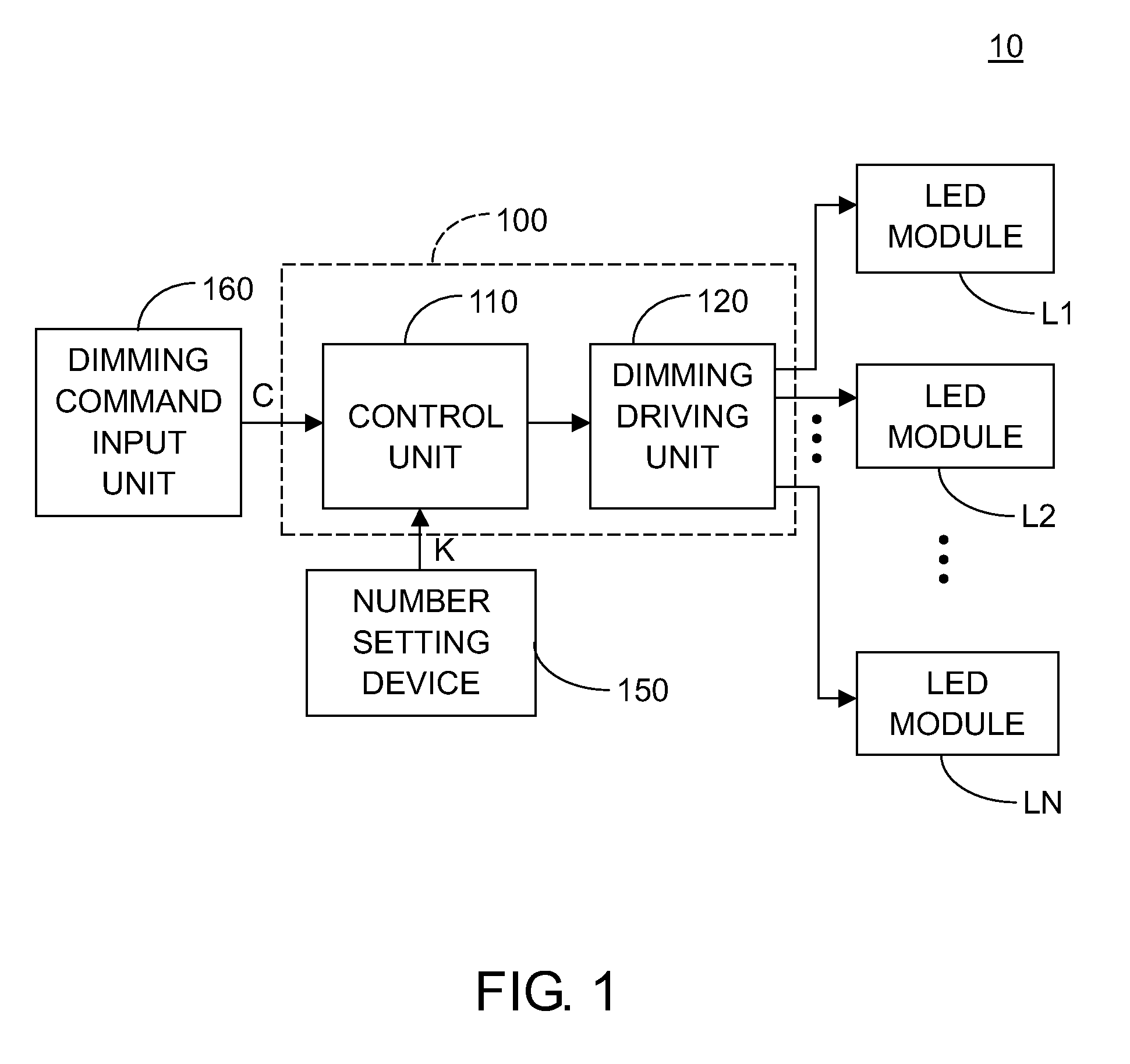
[0019]Referring to FIG. 1, it is a lighting system using a dimming control apparatus according to a first embodiment. As indicated in FIG. 1, the lighting system 10 includes a dimming control apparatus 100 and at least one of the LED modules L1 to LN, wherein N denotes the number of LED modules which are actually used with N≧1. In the present embodiment, a plurality of LED modules are used for exemplification, but the disclosure is not limited thereto. In response to a dimming command C and a number K, the dimming control apparatus 100 can generate K addressable sub-dimming commands corresponding to K LED modules to provide dimming control to the K LED modules individually, such as dimming control of either 0% or 100%, or dimming control with dimming levels from 0 to 100%, wherein the number K indicates the number of LED (lamp) modules that may be employed. The dimming control apparatus 100 outputs a plurality of dimming driving signals corresponding to K LED modules in response to ...

second embodiment

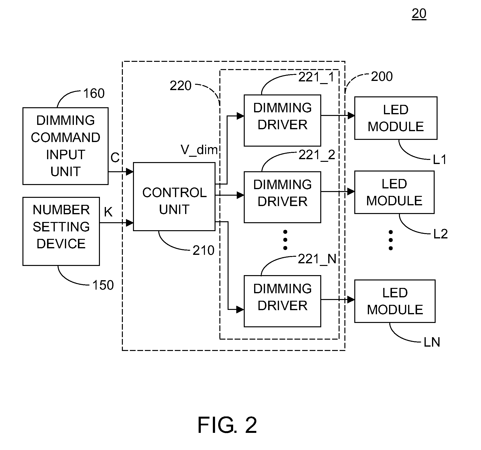
[0027]FIG. 2 shows a lighting system using a dimming control apparatus according to a second embodiment. In FIG. 2, the dimming control apparatus 200 of the lighting system 20 includes a control unit 210 and a dimming driving unit 220, wherein the dimming driving unit 220 further includes at least one of the dimming drivers 221_1 to 221_N with N≧1. In the present embodiment, a plurality of dimming drivers are used for exemplification, but the disclosure is not limited thereto. Each of the dimming drivers 221_1 to 221_N has an output terminal coupled to one of the LED modules L1 to LN in one-to-one manner. Since the LED modules L1 to LN may support different driving methods, each of the dimming drivers 221_1 to 221_N, according to the needs in practical application, can be implemented by digital dimming control (i.e., using PWM dimming) or analog dimming control such as a direct current voltage control circuit, or a circuit integrated with both the digital and analog approaches. The ...

third embodiment

[0028]The control unit of the dimming control apparatus can be realized by a processing unit, e.g., a central processing unit (CPU). The dimming driving unit can be realized by a pulse width modulation (PWM) control unit. The dimming driving signals outputted from the PWM control unit are PWM signals. FIG. 3 shows a lighting system using a dimming control apparatus according to a third embodiment. In FIG. 3, the dimming control apparatus 300 of the lighting system 30 includes a communication module 310, a processing unit 320 and a PWM control unit 330. The dimming control apparatus 300 can be realized by internal circuitry of a microcontroller, such as a single-chip microcontroller, e.g., 8051 or the like. In this embodiment, the communication module 310 can be realized by such as an RS-232 or other serial or parallel communication interface for receiving the dimming command C. After the processing unit 320 obtains a dimming command C via the communication module 310, the dimming co...


PUM


Abstract

A lighting system, a dimming control apparatus, and a dimming control method are provided. The dimming control apparatus includes a control unit and a dimming driving unit. In response to a dimming command and a number, the control unit decodes the dimming command into a plurality of sub-dimming commands. The dimming driving unit has a plurality of output terminals for coupling to a plurality of lamp modules. According to the sub-dimming commands, the control unit controls the dimming driving unit to output a plurality of dimming driving signals corresponding to the lamp modules to adjust the brightness of each lamp module individually.

Description

[0001]This application claims the benefit of U.S. provisional application Ser. No. 61 / 372,279, filed Aug. 10, 2010, and the benefit of Taiwan application Serial No. 99143317, filed Dec. 10, 2010, the subject matters of which are incorporated herein by reference.BACKGROUND[0002]1. Technical Field[0003]The disclosure relates in general to a dimming control apparatus and a method thereof, and more particularly to a dimming control apparatus applicable to light emitting diode lamp modules and a method thereof.[0004]2. Description of the Related Art[0005]While energy saving issues are widely concerned around the world, one of the important parts is to find alternatives replacing the conventional illumination. Light emitting diode (LED) related technologies are now a focus of research and development since LEDs, as the alternative, have the advantages of energy efficiency and low power consumption. However, the development and popularity of LED technologies encounter bottlenecks and they ...

Claims


Application Information

Patent Timeline
Patent Type & Authority Patents(United States)
IPC IPC(8): H05B41/16H05B37/00
CPCH05B33/0854H05B37/0254H05B45/10H05B47/18
Inventor LI, HUNG-CHUNYU, WUN-LONG
Owner IND TECH RES INST
Learn More