Coating process for the coating of an interior of a pipework system as well as a sub-distributor and a working equipment for the treatment of a pipework system

Inactive Publication Date: 2013-11-12
CEC SYST
View PDF14 Cites 0 Cited by
  • Summary
  • Abstract
  • Description
  • Claims
  • Application Information

AI Technical Summary

Benefits of technology

The new preferred working process described in the patent text involves reversing the direction of fluid-flow through the pipe system at least once during the process. This allows for a better cleaning, draining, and drying of the system, particularly in the bendings. The process is also gentle and can be worked with less blasting pressure, while still effectively cleaning the bendings.

Problems solved by technology

The pipes establishing the pipelines for hot water can corrode and rust, too.
Regarding buildings, a frequently given coating problem is that no building plans for the sanitary pipeline system are available.
But it happens that the pipes used have an inner diameter which is completely or partly greater than assumed so that the calculated amount of coating material is not sufficient and a greater amount of coating material would be necessary for a perfect coating.
Also the contrary happens in practice, namely the amount of epoxy resin was calculated to much because the pipes are completely or partly thinner than assumed, or the length of the pipes is actually shorter than assumed, leading to that too much coating material is blown into a particular pipe section so that the inner surface of the pipe is coated too thick, or in an extreme example the pipe is clogged by the coating material.
Regarding the existing processes, there is no possibility to determine whether the pipeline is perfectly coated by the coating material, or whether the thickness of the coating has the preset reference value, respectively.
But also the preparation processes known from the state of the art which must be carried out beforehand the actual coating process have disadvantages not being eliminated until now.
Strongly related problems are present at the following sand blasting of the pipework system.
Regarding this, in particular the bendings are often only insufficiently cleaned by the sand blasting process or critical locations are reached not at all.
In addition, the known processes have to work with high blasting pressures, in particular to get the problems at bendings under control, which, in case of thin or already strongly worn-out pipes, leads very often to the situation that the pipes are positively shot-through at the bendings by the sand blasting process, in turn leading to that the masonry in which the pipes are installed must be broken open, and the old pipes must be replaced by new ones, what actually should be avoided by the coating process.
Problems similar to the afore described in connection with the draining of the pipework system also consequently arise when dedusting the pipework system which must be done after the sand blasting process and before coating.

Method used


Image

  • Coating process for the coating of an interior of a pipework system as well as a sub-distributor and a working equipment for the treatment of a pipework system
  • Coating process for the coating of an interior of a pipework system as well as a sub-distributor and a working equipment for the treatment of a pipework system
  • Coating process for the coating of an interior of a pipework system as well as a sub-distributor and a working equipment for the treatment of a pipework system

Examples


Embodiment Construction

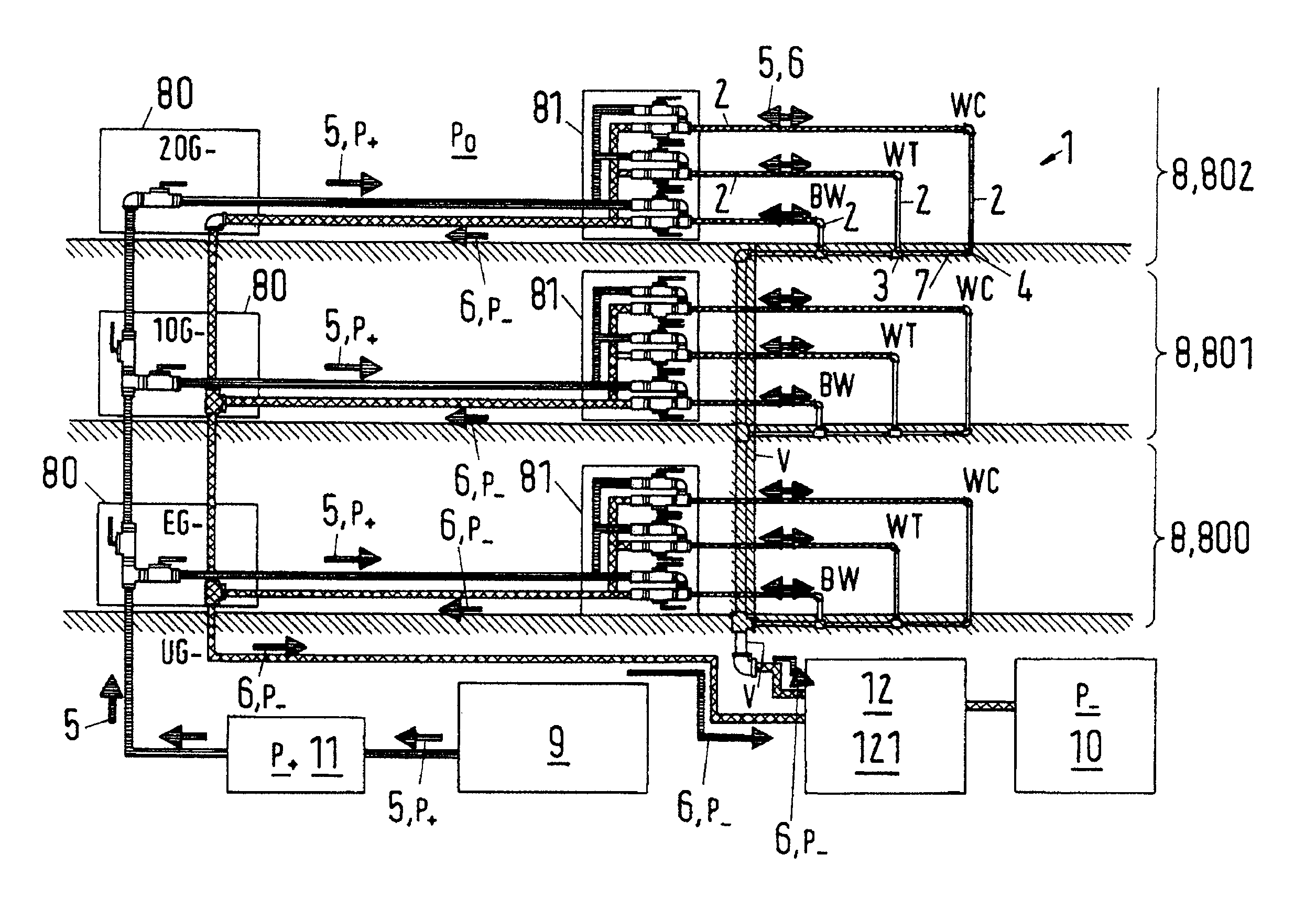
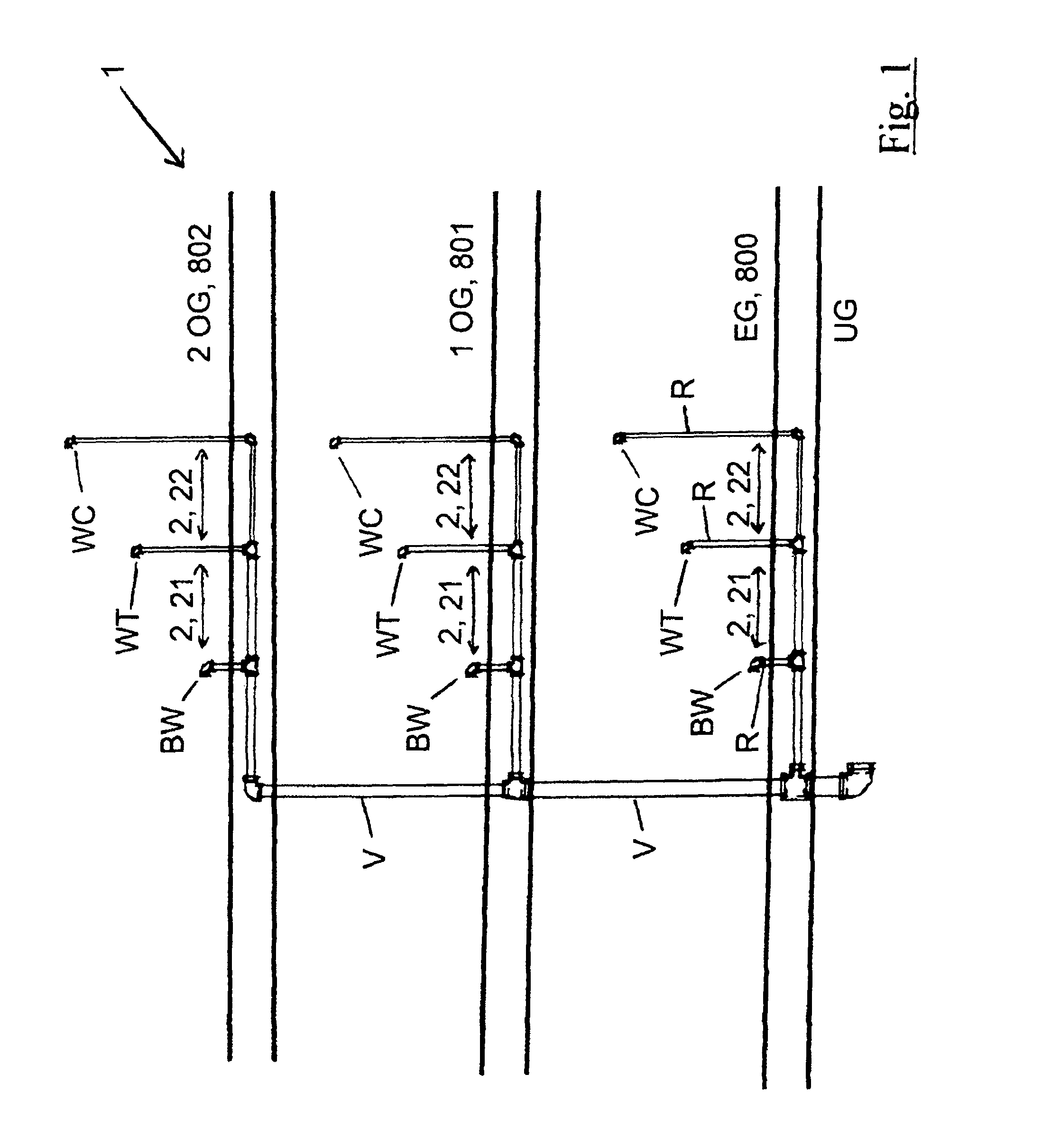
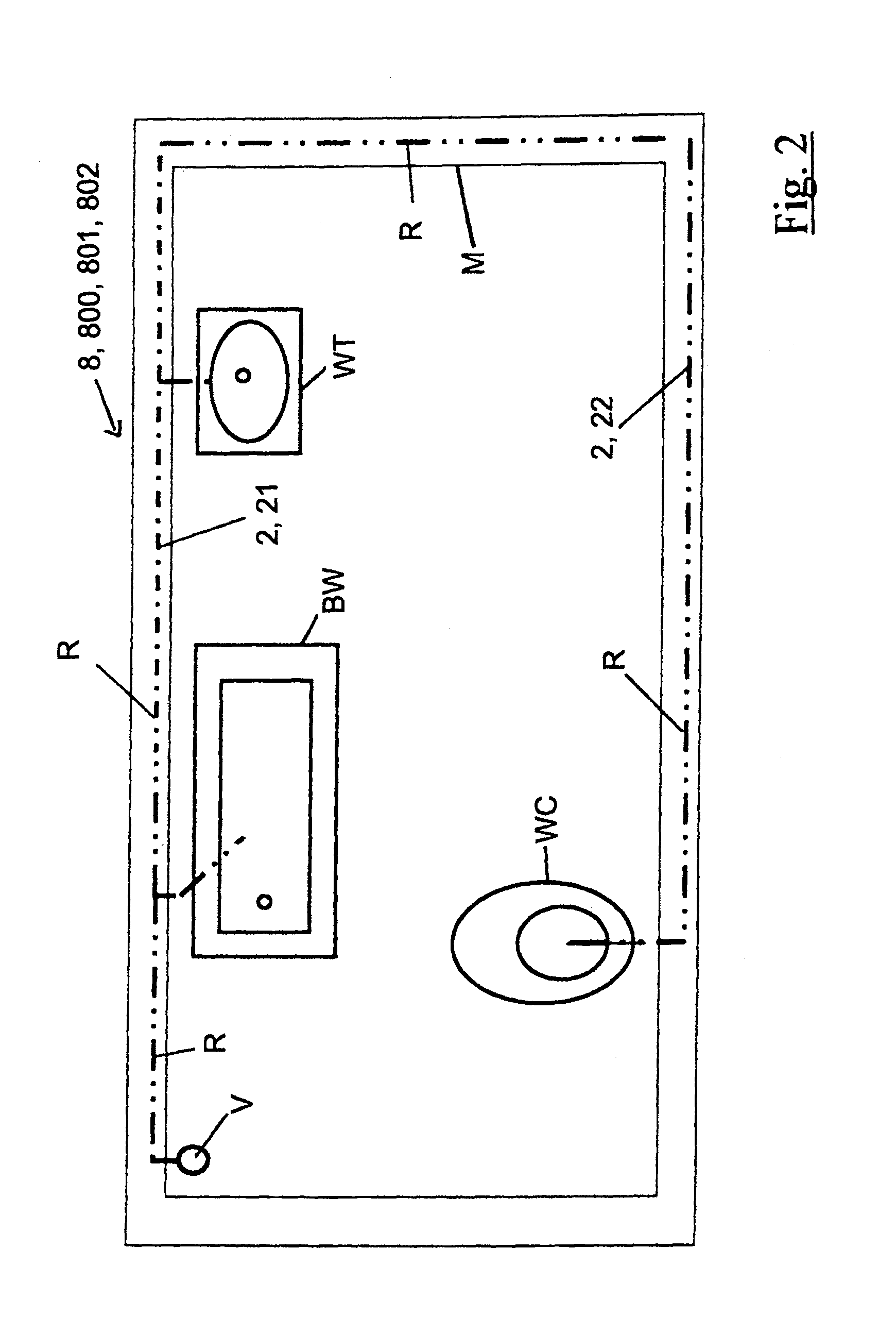
[0091]In order to better understand the invention, in the following an entire renovation process of a pipework system 1 is schematically explained with the help of a cold water installation 1 of a building, in which the installation extends over four floors, namely extending over the basement UG, the first floor EG, the first upper floor 1OG and the second upper floor 2OG.

[0092]It goes without saying that the invention in no means restricted to the renovation of cold water installations 1 of buildings extending over three floors, but is also related to the renovation of all kinds of pipework systems 1, for to a hot water pipework system 1, a circulation pipework system 1, a pipework system for a heating installation 1, in particular a floor heating installation 1, a gas pipework system 1, a wastewater pipework system 1, a water pipework system 1 for a roof, a pipework system 1 for a swimming-pool, a pipework system 1 for pressurized air, a pipework system 1 for distributing oil, whe...


PUM

PropertyMeasurementUnit
Pressureaaaaaaaaaa
Flow rateaaaaaaaaaa
Distanceaaaaaaaaaa

Abstract

A coating process for the interior of a pipework system, which includes a subsystem having a first part-system and a second part-system coupled to the first part-system, wherein the part-system can be pressurized by a pressure difference via a first connection of the first part-system and via a second connection of the second part-system, and wherein the first connection of the second part-system is identical to the second connection of the first part-system. In a second process step the first part-system is pressurized in such a way that a fluid-flow of the coating material is established through the first part-system and then the first connection of the second part-system is pressurized after the coating material leaves the second connection of the first part-system so that the first part-system and the second part-system is consecutively fed with the coating material.

Description

CROSS-REFERENCE TO RELATED APPLICATIONS[0001]This application is a National Stage of International Application No. PCT / EP2008 / 060795 filed Aug. 18, 2008, the disclosure of which is incorporated herein by reference.BACKGROUND OF THE INVENTION[0002]The invention relates to a coating process for the coating of an interior of a pipework system, as well as to a sub-distributor and a working equipment for the treatment of a pipework system in accordance with the preamble of the independent claim of the respective category.[0003]Such processes are used for drying oxidizing or otherwise corroding water pipes in buildings, for derusting them by means of sand blasting, and for coating them subsequently with an epoxy resin coating or with an other plastic layer.[0004]Mostly, water pipes of a building are subdivided in several pipelines. A typical example is a pipeline in a plumbing unit in an apartment or in a house. Water pipes for cold water constitute a first pipeline leading to a water-clo...

Claims


Application Information

Patent Timeline
IPC IPC(8): B05D7/22C22C16/00
CPCB05D7/222E03B7/006F16L58/1009B05D2254/04B05D2504/00Y10T137/86815
Inventor OHANESSIAN, ROBEN
Owner CEC SYST
Why Eureka
Try Eureka