
Motor vehicle outside door handle with a sensor module

a sensor module and motor vehicle technology, applied in the direction of securing communication, electrical devices, program control, etc., can solve the problems of negative influence on the sensitivity of the sensor, relatively complicated assembly, etc., and achieve the effect of simple production, easy cover and faster performan

Active Publication Date: 2013-11-05
HUF HULSBECK & FURST GMBH & CO KG
View PDF11 Cites 6 Cited by
  • Summary
  • Abstract
  • Description
  • Claims
  • Application Information

AI Technical Summary

Benefits of technology

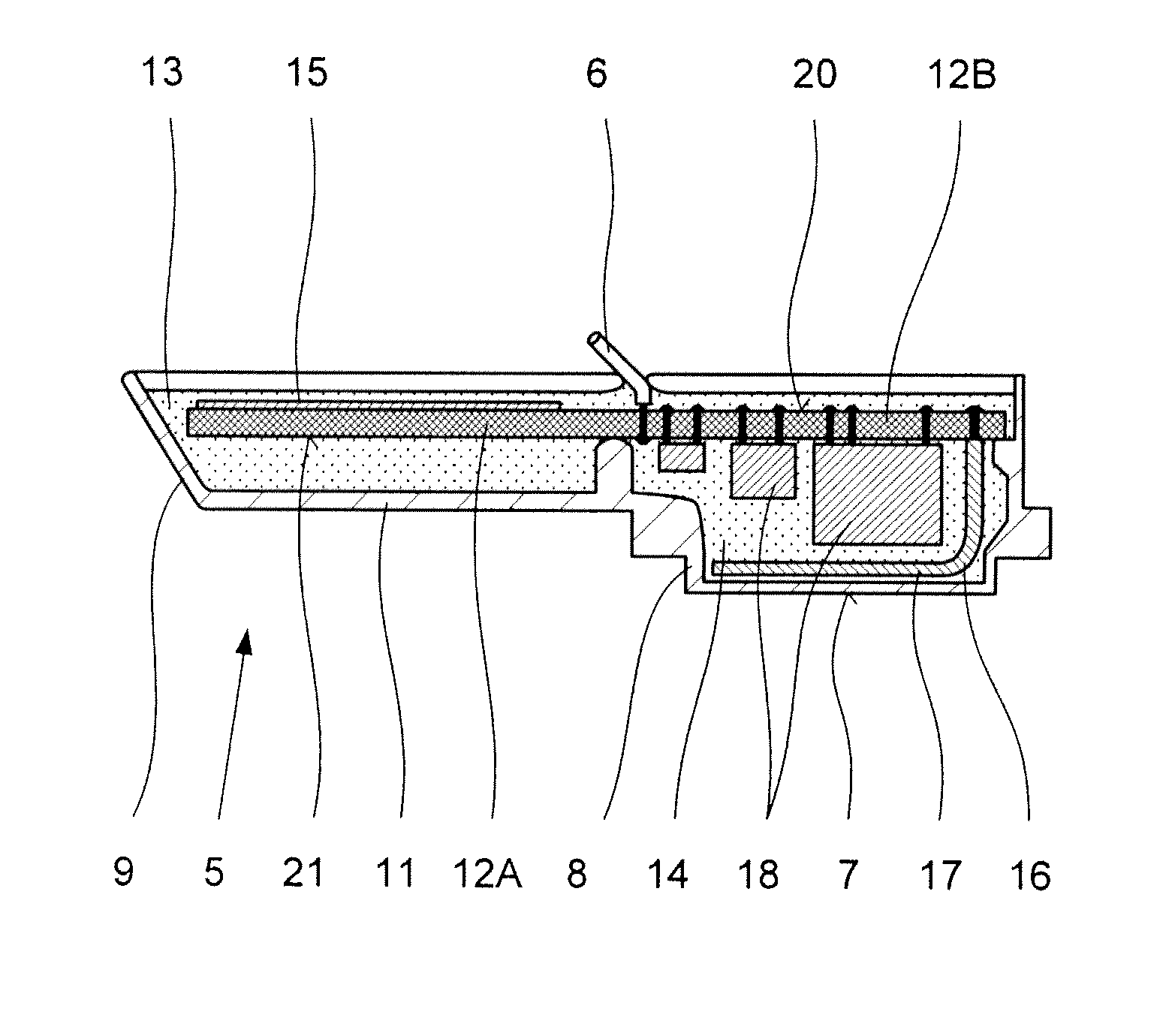
[0007]The fact that all sensor components are housed in the compact sensor module and the manner in which the sensor module is formed permit simple production, since the circuit is easily covered by simply filling the plastic tub with pourable material; furthermore the process of pouring into a plastic tub which is open on one side can be performed more quickly than the known process of pouring into a door handle in a longitudinal direction. Furthermore, the sensor module allows higher reliability, since the open side of the plastic tub is the only surface that is at risk of leaks.
[0008]A preferred further embodiment consists of a form wherein the first sensor electrode is formed by a first metal body that is mounted on the conductor plate or by a metallization layer of the conductor plate, that components of the evaluation circuit and a second metal body which serves as a second sensor electrode are mounted on the conductor plate, and that the second metal body is arrayed with a gap from the conductor plate and protrudes into a hollow space in the floor wall of the plastic tub which is adapted to the dimensions of the second metal body. This has the advantage that it becomes easier to move the second sensor electrode away from the first sensor electrode and therefore easier to separately detect the response of the sensors, and that the second sensor electrode can be moved closer to the surface of the activating surface, so that it is possible to set a lower sensitivity of the second sensor.
[0009]A further preferred embodiment consists of a form in which the sensor module is arrayed in the inner space of the outer door handle so that a wall segment of the bottom wall of the plastic tub of the sensor module which protrudes to the outside passes through an opening in the wall of the outer door handle, herein defining the specified location for triggering the locking process. This particularly contributes to increased reliability, since the protruding wall segment which passes through the wall of the outer door handle directly forms the activating surface of the sensor triggering the locking process which must be touched by the operator. It is not possible for a film of moisture to form within the sensor module, and the moisture film which may form on the outer surface of the bottom wall of the sensor module is directly wiped away by the body part of the operator, or pushed away to a degree which makes it possible to securely detect the touch. A lasting persistence of an interfering moisture film between the touch surface and the sensor electrode is no longer possible. A preferred further form of this embodiment consists of a form wherein the first sensor electrode is formed by a first metal body that is mounted on the conductor plate or by a metallization layer of the conductor plate, that components of the evaluation circuit and a second metal body which serves as a second sensor electrode are mounted on the conductor plate, and that the second metal body is arrayed with a gap from the conductor plate and protrudes into a hollow space in the floor wall of the plastic tub which is adapted to the dimensions of the second metal body, wherein the indentation which receives the second metal body is arrayed adjacently to the outwardly protruding wall segment of the sensor module. The second metal body preferably possesses a level sheet metal segment which lies flat against a level inner surface of the bottom wall in the indentation. Then the thickness of the bottom wall in this area determines the distance between the metal surface of the sensor and the operator's finger when operating the locking sensor.
[0010]A preferred further embodiment of the outer motor vehicle door handle consists of a form wherein the first sensor electrode is formed by a metallization layer on a first surface of the conductor plate and the components of the evaluation circuit are mounted on the opposite second surface of the conductor plate. This permits a smaller construction size of the sensor module. Herein the second surface of the conductor plate preferably faces the bottom wall of the plastic tub. Therefore, the first surface of the conductor plate which bears the first sensor electrode is then arrayed directly below the surface of the pourable mass on the open side of the plastic tub. The construction space within which the components of the evaluation circuit are located results in a distance of the first sensor electrode that is arrayed on the conductor plate from the second sensor electrode that is arrayed on the side of the components in the indentation of the bottom wall, and therefore disconnects them.
[0011]A preferred further embodiment of the outer motor vehicle door handle consists of a form wherein the conductor plate possesses two conductor plate segments which are arrayed behind each other in the plastic tub when the sensor module is mounted in the longitudinal direction of the handle, wherein one conductor plate bears the metallization layer that serves as the first sensor electrode and the second conductor plate segment bears the components of the evaluation circuit and the second metal body. This also results in a greater distance between the two sensor electrodes, which permits better evaluation and differentiation of the capacity changes detected by the sensor electrodes. The components of the evaluation circuit are preferably mounted on the second surface of the conductor plate in such a manner that they are at least partially covered by the second metal body. This permits a smaller construction size of the sensor module.

Problems solved by technology

Herein it is possible that a film of moisture forms between the metal electrode and the inner surface of the door handle wall, negatively influencing the sensitivity of the sensor.
This assembly is relatively complicated.

Method used


Image

  • Motor vehicle outside door handle with a sensor module
  • Motor vehicle outside door handle with a sensor module
  • Motor vehicle outside door handle with a sensor module

Examples


Embodiment Construction

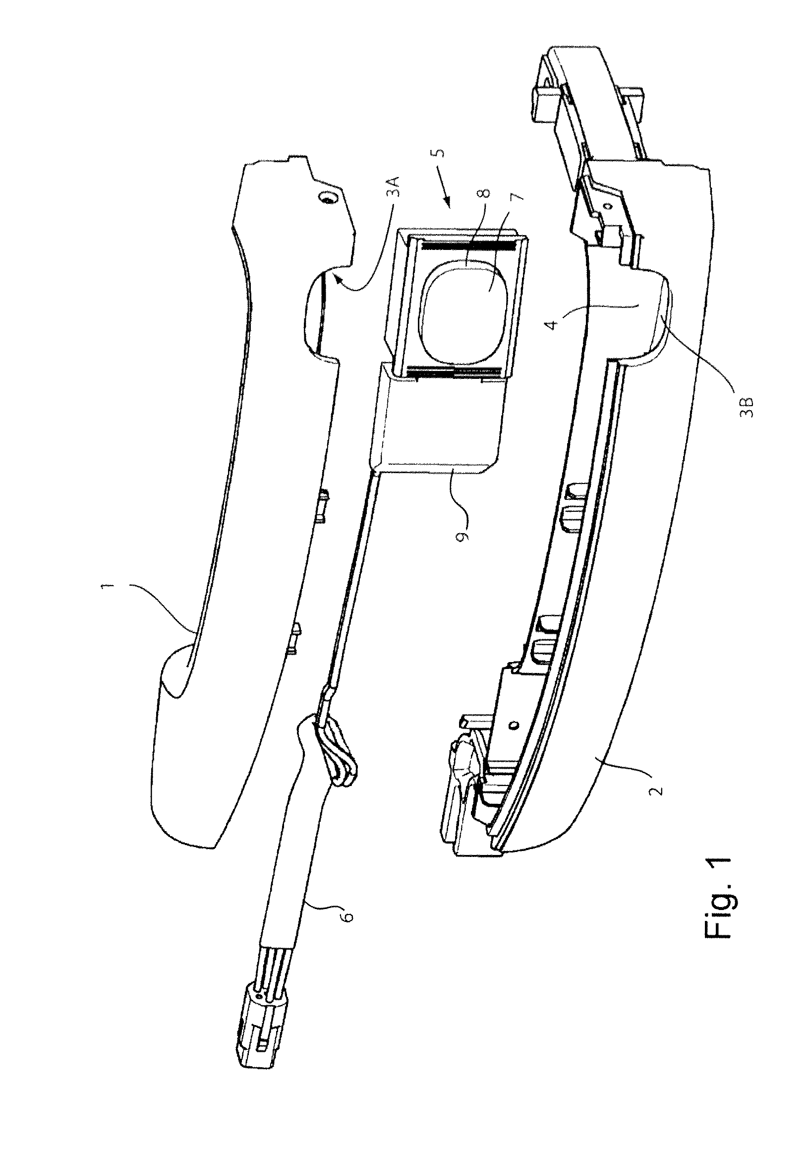
[0018]In the preferred exemplary embodiment of the outer motor vehicle door handle in accordance with the invention as shown in FIG. 1, a sensor module 5 is placed within an inner space 4 between two handle halves 1, 2. Input leads 6 which are connected with the sensor module 5 are brought through the inner space 4 within the handle halves 1 and 2 in such a manner that they come out of the handle behind a door wall (not shown in FIG. 1) within the interior of a motor vehicle door. There, the input leads 6 are connected to a power supply and control device (also not shown).

[0019]The sensor module 5 consists of a plastic tub 9 which is open towards a side not visible in FIG. 1, in which a first sensor electrode of a first capacitive sensor (for triggering an unlocking process when detecting the entry of a body part of the operator into an inner space formed between the outer door handle and a door wall), a second sensor electrode of a second capacitive sensor (for triggering a locking...


PUM


Abstract

A motor vehicle outside door handle with a wall surrounding an interior space, a first sensor electrode of a first capacitive sensor for triggering a final locking operation, a second sensor electrode of a second capacitive sensor for triggering a locking operation, and an evaluation circuit, which is connected to the first sensor electrode. The second sensor electrode is arranged in the interior space. The first sensor electrode, the second sensor electrode and the evaluation circuit are accommodated in a single sensor module which can be inserted into the interior space. The sensor module has a flat plastic trough which has a bottom wall and is open on one side. A printed circuit board provided with connecting cables is placed into the plastic trough filled with a plastics compound. The sensor electrodes are formed by metal-coated layers of the printed circuit board or by metal bodies mounted on the printed circuit board.

Description

[0001]This is a non-provisional application claiming the benefit of International application number PCT / EP2009 / 051087 filed Jan. 30, 2009.BACKGROUND OF THE INVENTION[0002]The invention concerns an outer motor vehicle door handle with a wall that surrounds an inner space, a first sensor electrode of a first capacitive sensor to trigger an unlocking process when detecting the approach of a part of the operator's body to a space that is formed between the outer door handle and a door wall, particularly when detecting the entry of a part of the operator's body into the space that is formed between the outer door handle and the door wall, a second sensor electrode of a second capacitive sensor to trigger a locking process when detecting the approach of a part of the operator's body to a specified location on an outer area of the outer door handle that faces away from the door wall, and an evaluation circuit that is arrayed in the inner space and connected to the sensor electrode and the...

Claims


Application Information

Patent Timeline
Patent Type & Authority Patents(United States)
IPC IPC(8): G08B29/00
CPCE05B81/76E05B85/16E05B81/77H03K17/955H03K2217/960755
Inventor PESCHL, ANDREASNEUHOFF, STEFANKILIAN, MARION
Owner HUF HULSBECK & FURST GMBH & CO KG
Learn More