Eureka AIR delivers breakthrough ideas for toughest innovation challenges, trusted by R&D personnel around the world.

Optical measuring cell and gas monitor

a measuring cell and optical technology, applied in the direction of instruments, separation of dispersed particles, separation processes, etc., can solve the problems of substantial gas consumption, and achieve the effects of small measuring cell volume, minimal maintenance, and long absorption path

Inactive Publication Date: 2013-10-29
SIEMENS AG
View PDF28 Cites 8 Cited by
  • Summary
  • Abstract
  • Description
  • Claims
  • Application Information

AI Technical Summary

Benefits of technology

This patent describes a device that uses a hollow fiber to measure gas absorption. The fiber is open at the front and allows the gas and light used for the measurement to enter from one end. The light is coupled in the fiber and can travel for several meters without significant loss. The device is sensitive to small amounts of gas and requires minimal flushing gas usage, resulting in a self-sufficient measuring apparatus. Additionally, the device can be made portable and highly sensitive using the compact components.

Problems solved by technology

Since conventional measuring cells usually have large volumes, depending on their application, being typically >100 cm3 to several liters, and a flushing gas volume which is a multiple of the measuring cell volume is needed for each flushing operation, then for continuously running or large numbers of measuring processes, this results in a substantial consumption of gas.

Method used


Image

  • Optical measuring cell and gas monitor
  • Optical measuring cell and gas monitor

Examples


Embodiment Construction

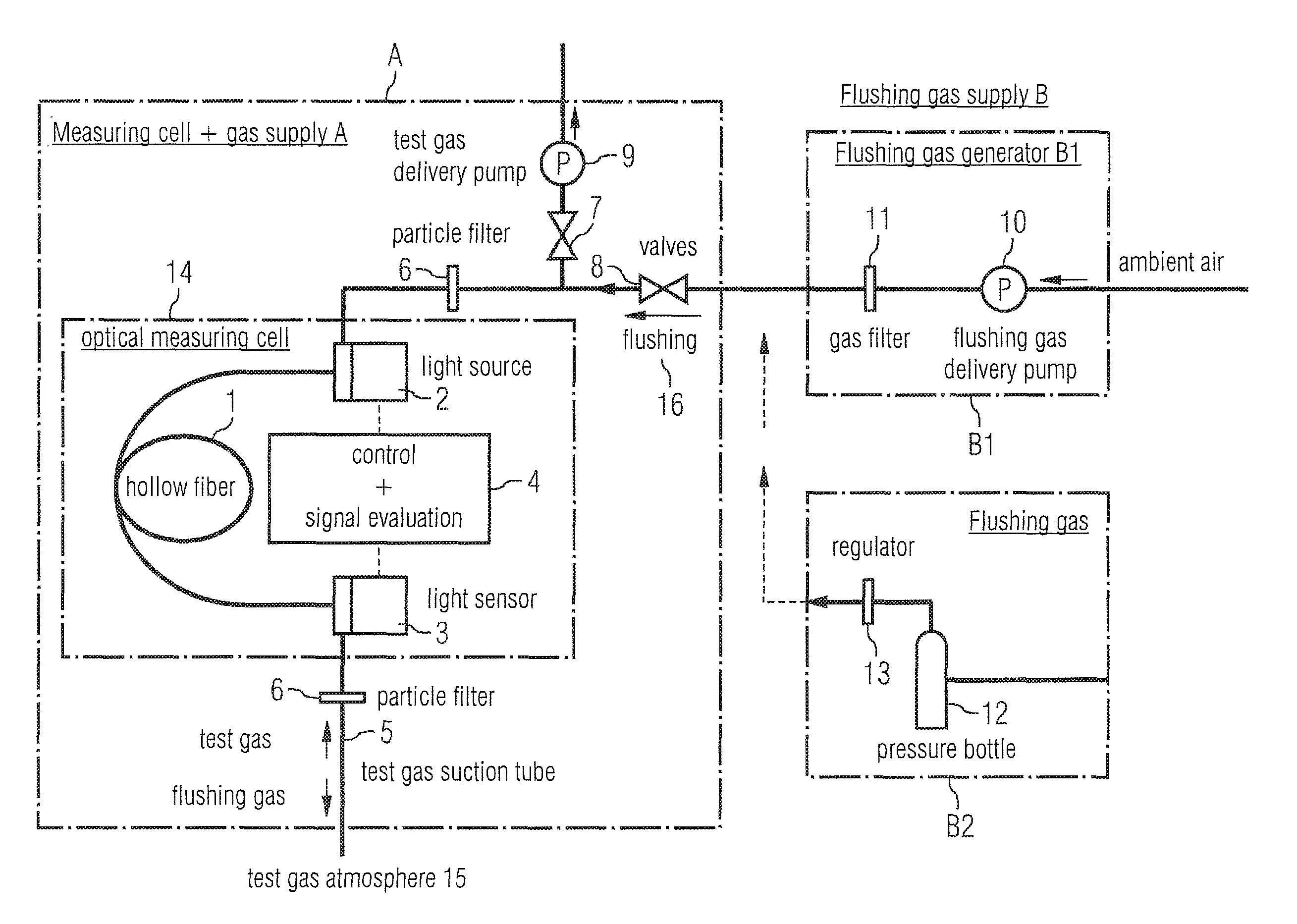
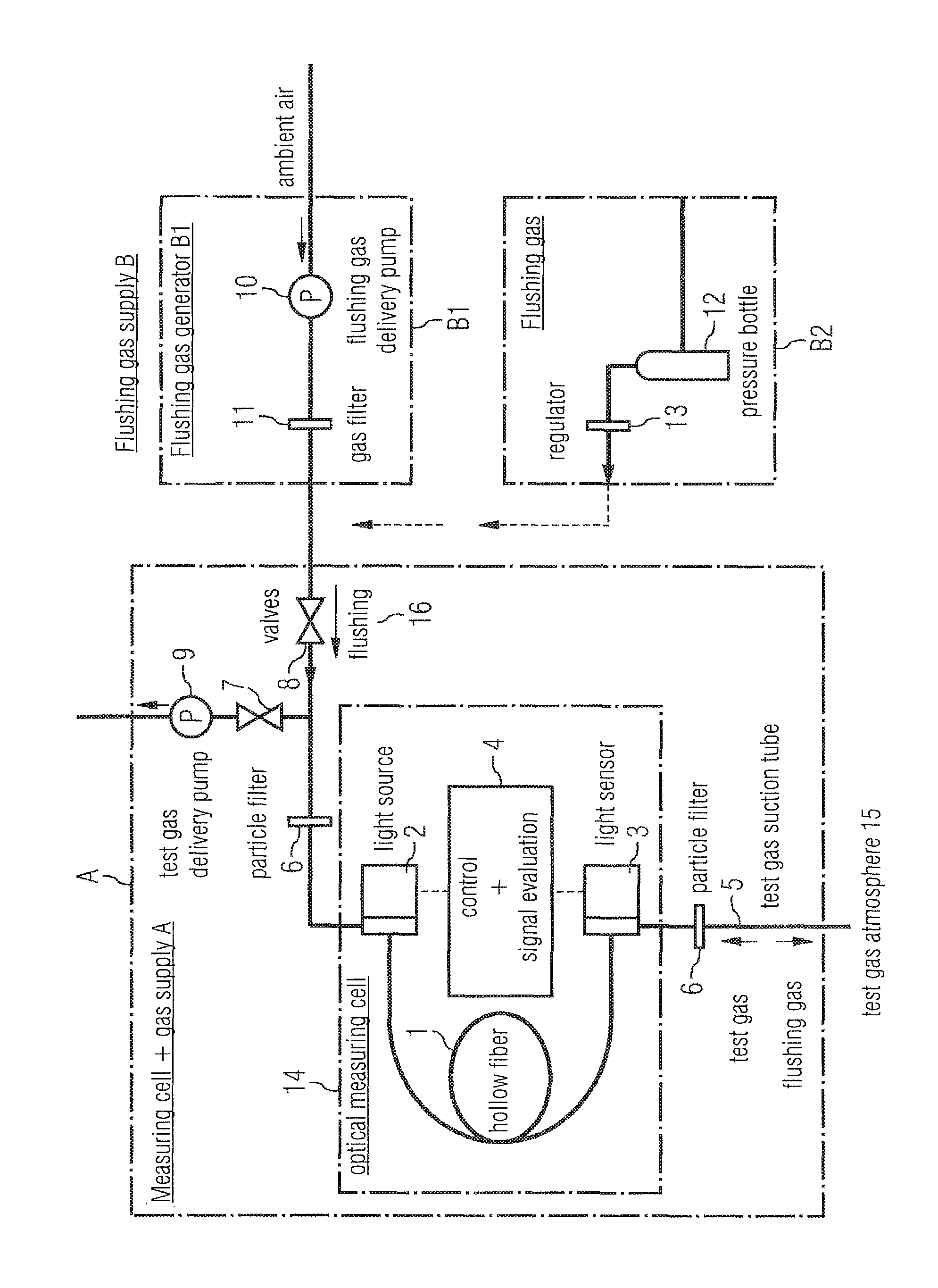
[0015]The FIGURE shows a measuring cell with a gas supply A, comprising an optical measuring cell 14 with a hollow fiber 1.

[0016]The FIGURE shows an exemplary embodiment of the invention in detail. The arrangement comprises the optical measuring cell 14, the test gas delivery system and the flushing gas delivery system as well as a flushing gas supply. The optical measuring cell comprises the hollow fiber 1 as the absorption measuring cell with the light source 2, the light detector 3 and the control and evaluation circuit 4.

[0017]The test gas delivery system comprises the test gas suction tube 5, optional fine-pored particle filters 6 and, following the hollow fiber 1, a valve 7 before the test gas delivery pump 9, as well as a gas outlet. A valve 8 closes off the measuring cell with the gas delivery A in the direction toward the flushing gas supply B. The flushing gas supply can comprise a compressed flushing gas bottle B2. However, the use of a flushing gas supply using a flushin...


PUM

PropertyMeasurementUnit
internal diameteraaaaaaaaaa
volumesaaaaaaaaaa
volumeaaaaaaaaaa

Abstract

An optical measuring cell for measuring gas absorption with a light source for introducing light into a measuring volume and a light sensor located approximately opposite the light source in the direction of light propagation and relative to the measuring volume for receiving light that is guided through the measuring volume is provided. The concentration of one or multiple target gases in the measuring volume is detected by an evaluation unit. The measuring volume is constituted by an internal volume of a hollow fiber having an internal diameter less than 1 mm.

Description

CROSS REFERENCE TO RELATED APPLICATIONS[0001]This application is the US National Stage of International Application No. PCT / EP2007 / 062481 filed Nov. 19, 2007 and claims the benefit thereof. The International Application claims the benefit of German Patent Application No. 10 2006 055 157.5 DE filed Nov. 22, 2006, both of the applications are incorporated by reference herein in their entirety.FIELD OF INVENTION[0002]The invention relates to an optical measuring cell and a gas monitor for gas absorption methods, and a gas monitor.BACKGROUND OF INVENTION[0003]In the fields of photometry and optical spectroscopy to determine the concentration of a gas component in a test gas by means of absorption measurement, the problem arises with the measuring sample cell that the transmission of the empty sample cell without any target gas present, and therefore without any absorption due to the target gas, must be known in order to be able to identify the target gas by evaluating the gas-dependent ...

Claims


Application Information

Patent Timeline
Patent Type & Authority Patents(United States)
IPC IPC(8): G01N21/00
CPCG01N21/05G01N21/31G01N21/3504B01D53/30G01N2021/0346
Inventor FLEISCHER, MAXIMILIANLAMPE, UWESTRZODA, RAINER
Owner SIEMENS AG
Why Eureka
Eureka Blog
Learn More