
Methods and devices for providing inspiratory and expiratory flow relief during ventilation therapy

a technology of inspiratory and expiratory flow and ventilation therapy, which is applied in the direction of valves, respirators, operating means/releasing devices, etc., can solve the problems of affecting the ventilation

Active Publication Date: 2013-10-29
BREATHE TECHNOLOGIES INC
View PDF1107 Cites 11 Cited by
  • Summary
  • Abstract
  • Description
  • Claims
  • Application Information

AI Technical Summary

Benefits of technology

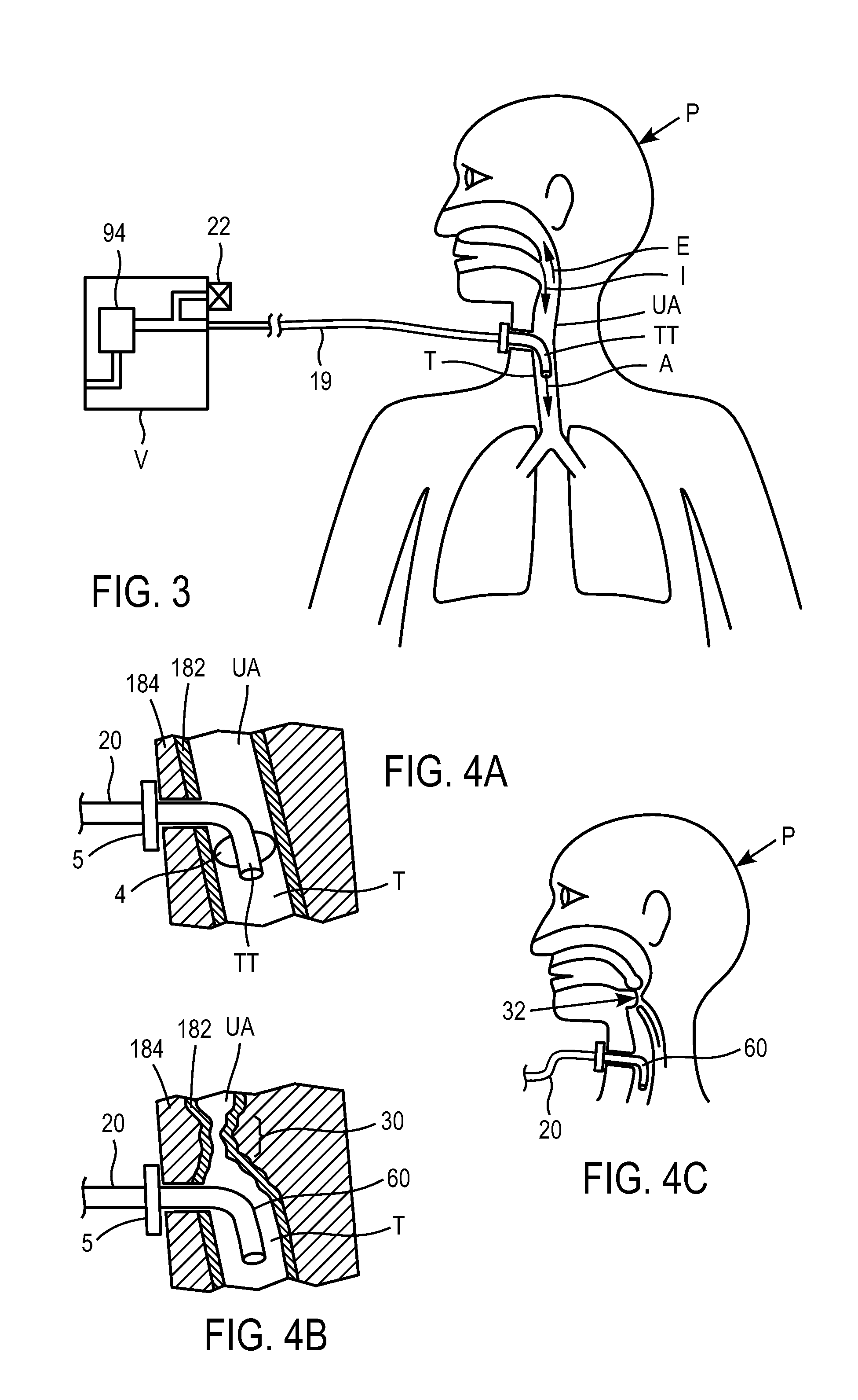
[0009]The current invention is an improvement over existing ventilation interfaces and ventilation modes. The invention may include a ventilation interface with a spontaneous breathing flow path such that the patient can breathe ambient air freely through the interface if needed, and in the event of an obstruction, the patient is provided an alternate route of inspiring and / or exhaling. The invention may also include providing pressure and flow relief mechanisms in the ventilation interface to avoid undesirable lung pressures or to maintain desired lung pressures.

Problems solved by technology

A number of problems can arise during ventilation.
In the case of mechanical ventilation, an obstruction can occur anywhere in the gas delivery circuit or breathing circuit.
Typically, such an obstruction in a mechanical ventilation system is annunciated by alarms, and an attending clinician is required to correct the problem, since the patient may not be capable of doing so.
In the case of respiratory support ventilation, the obstruction can occur anywhere in the gas delivery circuit or breathing circuit, as well.
However, in some systems or some situations, that the patient may exhale through the gas delivery circuit.
If any event such these, or other airway-obstructing event, occurs, the patient is obstructed or restricted from being able to spontaneously breathe, and the amount of gas received from the ventilator through the open gas delivery circuit may not be enough to sustain respiration.

Method used


Image

  • Methods and devices for providing inspiratory and expiratory flow relief during ventilation therapy
  • Methods and devices for providing inspiratory and expiratory flow relief during ventilation therapy
  • Methods and devices for providing inspiratory and expiratory flow relief during ventilation therapy

Examples


Embodiment Construction

[0204]FIG. 1 illustrates a prior art conventional ventilation system, commonly known as a continuous mechanical ventilation (CMV) system, in which the ventilator (V) is connected to the patient (P) with a dual limb breathing circuit (2) and delivers gas to the patient via an inspiratory limb (IL), and gas is exhaled from the lung back an expiratory limb (IL) through an exhalation valve (22). A typical patient ventilation interface is an endotracheal tube (ETT) with a tracheal tube cuff (4), such that the patient's lungs are closed off from ambient air and are only connected to an air source through the ventilator breathing circuit. The ventilator in CMV systems typically includes one or more ambient relief valves to prevent over pressurization of the lung if an obstruction or high pressure event occurs and to enable access to ambient air if a ventilator failure occurs. The ventilator can include an inspiratory relief valve (8) so that the patient, if they have any breath effort capa...


PUM


Abstract

Respiratory support and / or controlled mechanical ventilation of a patient are provided. A ventilation apparatus may include a ventilator, a transtracheal prosthesis, and a respiratory relief device. The transtracheal prostheses and ventilation catheter may be arranged such that the patient can breathe freely through the upper airway and / or the tracheal prostheses. Respiratory sensors may measure a breathing rate, lung pressure, airway pressure, or a combination thereof. Pulses of gas may be provided to the patient through the ventilation catheter during inspiration. The pulses may have a first volume while the patient breathes normal and a second volume when the sensors detect a cessation of breathing or reduction in breathing volume. The second volume may be provided at 1-5 times the normal breathing rate, with a volume 25-500% times the first volume, or both.

Description

[0001]This application claims the benefit of U.S. Provisional Application No. 60 / 960,370 filed Sep. 26, 2007, which is incorporated by reference herein in its entirety.FIELD OF THE INVENTION[0002]This invention relates to ventilation therapy for persons suffering from respiratory impairment and breathing disorders, such as chronic obstructive pulmonary disease (COPD), pulmonary fibrosis, acute respiratory distress syndrome (ARDS), neuromuscular impairment, and sleep apnea.[0003]The present invention relates specifically to providing a means for exhalation and inspiration through a ventilation tube in the event that an obstruction occurs which would otherwise prevent the patient from adequately inhaling or exhaling through their normal upper airway ventilation route.BACKGROUND OF THE INVENTION[0004]There are two general types of control systems for ventilators, or ventilation, known in the art. A first type of ventilation control system delivers gas to a patient based on a frequency ...

Claims


Application Information

Patent Timeline
Patent Type & Authority Patents(United States)
IPC IPC(8): A61M16/00
CPCA61M16/0096A61M16/0463A61M16/0465A61M16/208A61M16/206A61M16/209A61M2016/0021A61M2016/0027A61M2016/0036A61M2230/10A61M2230/205A61M2230/432A61M2230/50A61M2230/60A61M2230/65A61M16/202
Inventor WONDKA, ANTHONYKAPUST, GREGORY
Owner BREATHE TECHNOLOGIES INC
Learn More