
Automated sequential planning of MR scans

a technology of mri and automatic planning, applied in the direction of nmr measurement, instruments, diagnostic recording/measuring, etc., can solve the problems of time-consuming operation, difficult to accurately image the anatomy of certain organs and parts of the body, and clinical images obtained by different operators will have different levels of quality, so as to control the quality of clinical mri images and save time

Active Publication Date: 2013-10-22
KONINK PHILIPS ELECTRONICS NV
View PDF31 Cites 16 Cited by
  • Summary
  • Abstract
  • Description
  • Claims
  • Application Information

AI Technical Summary

Benefits of technology

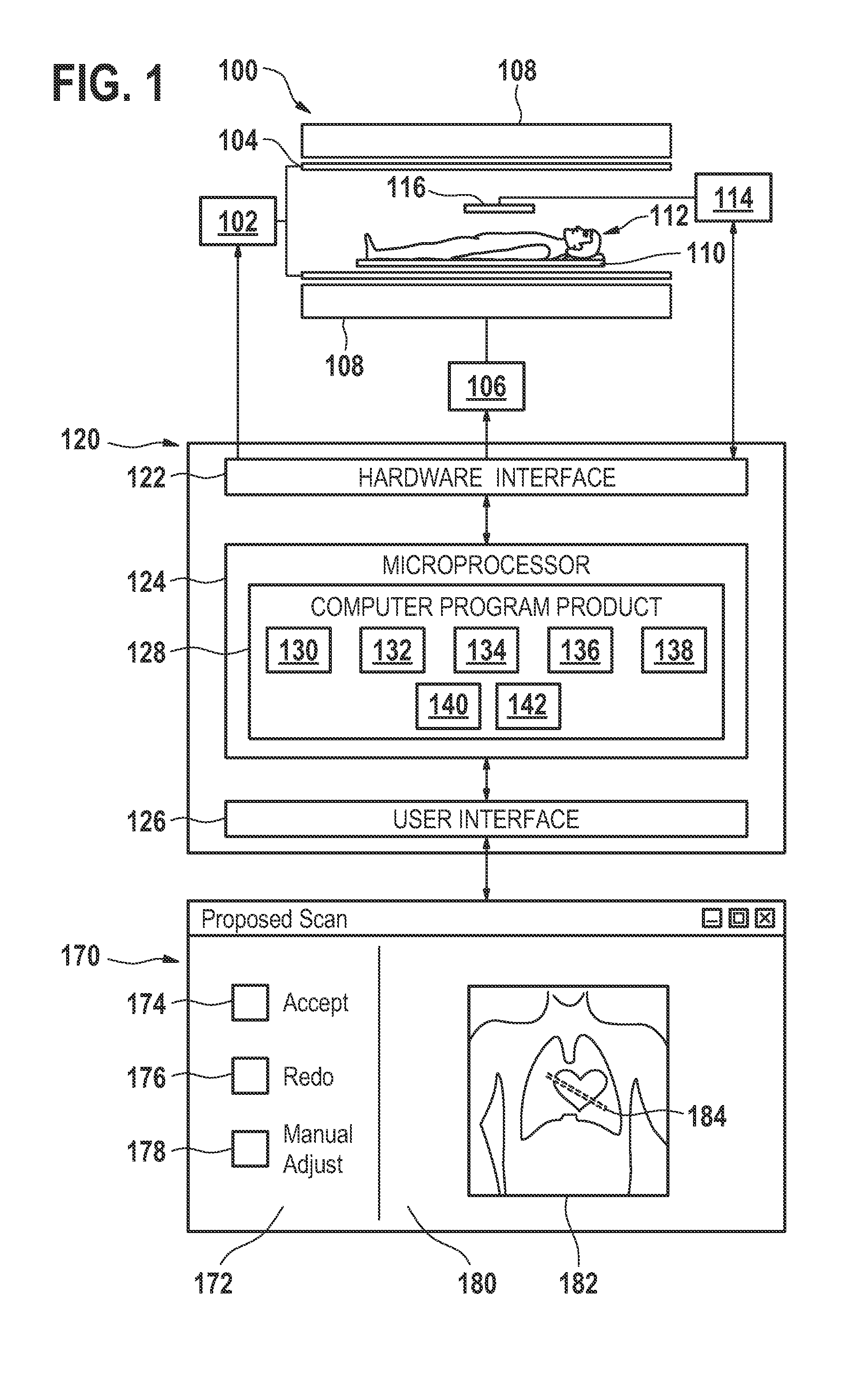
The invention provides a way to automatically plan MRI scans, which reduces errors and training requirements for operators. It also avoids differences in results between operators. The user interface allows for manual modification of the rejection data, which is then used to generate a modified set of planning data. This saves time and eliminates the need for repetition of the entire process.

Problems solved by technology

The anatomy of certain organs and portion of the body can also be challenging to image properly.
In practice, navigator beam, a shim volume or other elements need to be orientated, which makes this a time consuming operation.
The difficulty with this is that the clinical images obtained by different operators will have differing levels of quality.
In addition, reproducibility of a clinical MRI image, e.g., in a follow up procedures, is difficult to achieve when setting the position and orientation of the stack of slices is performed manually.
When an operator produces clinical images of poor quality, they will need to be redone.
This is of course expensive for hospitals, and raises the cost of having MRI examination done on a patient.

Method used


Image

  • Automated sequential planning of MR scans
  • Automated sequential planning of MR scans
  • Automated sequential planning of MR scans

Examples


example

Clinical Wrist Imaging

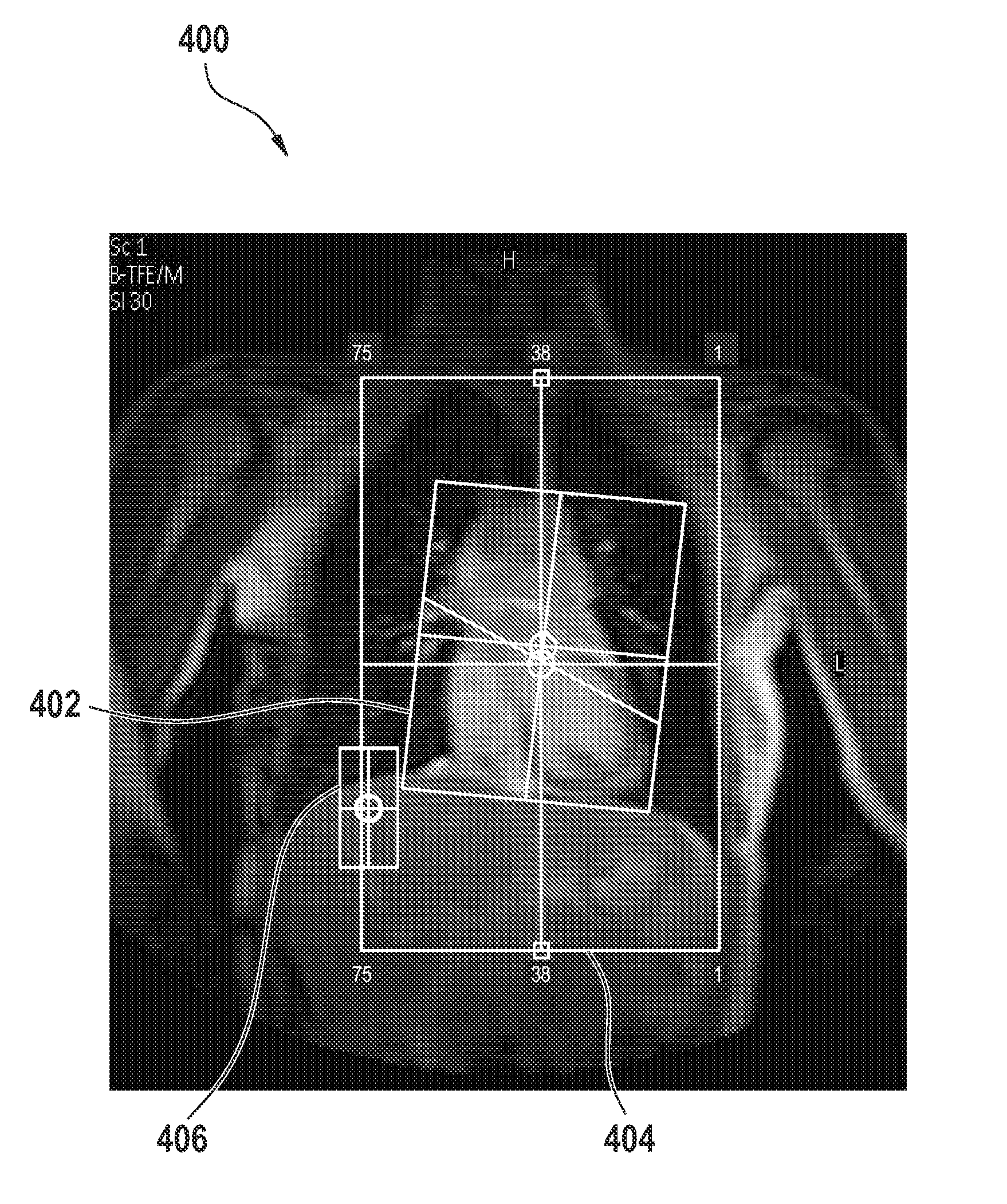
[0083]This example demonstrates an embodiment of the invention where two sequential, automated survey scans are performed and are used to automatically plan the acquisition of clinical MRI images. This example details a fully automated acquisition of clinical MRI images of the wrist. This is clinically relevant since the positioning of the wrist using the light visor is time consuming and error prone. Because of these difficulties, a first survey is often acquired only to locate the wrist. Then, a second survey that zooms in on the wrist region is acquired which is used for the actual planning of clinical images.

[0084]Automated sequential planning relieves the operator of the task of manually zooming to the correct wrist location and of planning the subsequent clinical image. The first survey is automatically processed to locate the wrist. A second zoomed survey is then used to plan the first clinical images.

[0085]In detail, an embodiment of the method consists...


PUM


Abstract

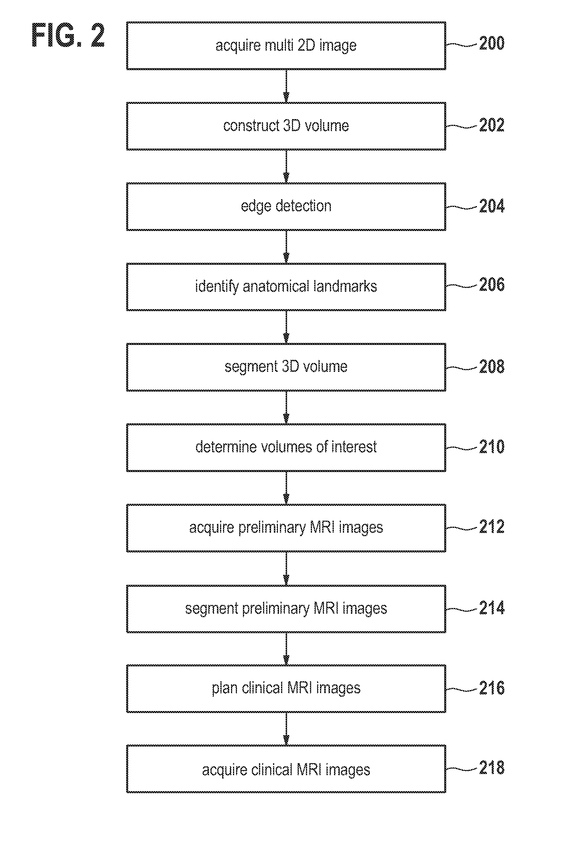
A method of acquiring at least one clinical MRI image of a subject comprising the following steps: acquiring a first survey image with a first field of view, the first survey image having a first spatial resolution,—locating a first region of interest and at least one anatomical landmarks in the first survey image, determining the position and the orientation of the first region of interest using the anatomical landmarks, the position and the orientation of the first region being used for—planning a second survey image,—acquiring the second survey image with a second field of view, the second survey image having a second spatial resolution, the second spatial resolution being higher than the first spatial resolution, generating a geometry planning for the anatomical region of interest using the second survey image,—acquiring a diagnostic image of the anatomical region of interest using the geometry planning.

Description

FIELD OF THE INVENTION[0001]The invention relates to a method, an apparatus, and a computer program product for automatically acquiring clinical MRI image data.BACKGROUND OF THE INVENTION[0002]A large static magnetic field is used by MRI scanners to align the nuclear spins of atoms as part of the procedure for producing images within the body of a patient. This large static magnetic field is referred to as the B0 field.[0003]During an MRI scan, Radio Frequency (RF) pulses generated by a transmitter coil cause perturbations to the local magnetic field, and RF signals emitted by the nuclear spins are detected by a receiver coil. These RF signals are used to construct the MRI images. These coils can also be referred to as antennas. Further, the transmitter and receiver coils can also be integrated into a single transceiver coil that performs both functions. It is understood that the use of the term transceiver coil also refers to systems where separate transmitter and receiver coils ar...

Claims


Application Information

Patent Timeline
Patent Type & Authority Patents(United States)
IPC IPC(8): G06K9/00
CPCG01R33/54G01R33/543G01R33/56383G01R33/5608G01R33/546
Inventor BERGMANS, CORNELIS JOHANNES FRANCISCUS MARIABYSTROV, DANIELHEESE, HARALD SEPPKOUWENHOVEN, MARCDEN HARDER, JOHAN MICHIELSIMONETTI, ARJAN WILLEMDE KOK, WENDY
Owner KONINK PHILIPS ELECTRONICS NV
Learn More