
Earphone microphone

a microphone and earphone technology, applied in the field of earphones/microphones, can solve problems such as difficulty in conducting smooth conversations

Active Publication Date: 2013-10-08
YAMAHA CORP
View PDF12 Cites 0 Cited by
  • Summary
  • Abstract
  • Description
  • Claims
  • Application Information

AI Technical Summary

Benefits of technology

The present invention provides an earphone microphone in a mobile phone that can accurately convert a user's speech into a sound signal with all the necessary frequency components to recognize consonants and vowels. This allows for smooth conversation over phones. Additionally, external sounds are utilized to compensate for higher frequency components that may be lost when a user's mouth emits sound. As a result, a sound signal is produced that contains all the necessary components for accurately perceiving the user's speech.

Problems solved by technology

Even when talkers' sounds transmitted inside their external auditory canals are transmitted to counterpart listeners / talkers over phones, it is difficult to conduct smooth conversations due to loss of frequency components prerequisite for discriminating human speeches.

Method used


Image

  • Earphone microphone
  • Earphone microphone
  • Earphone microphone

Examples


first embodiment

1. First Embodiment

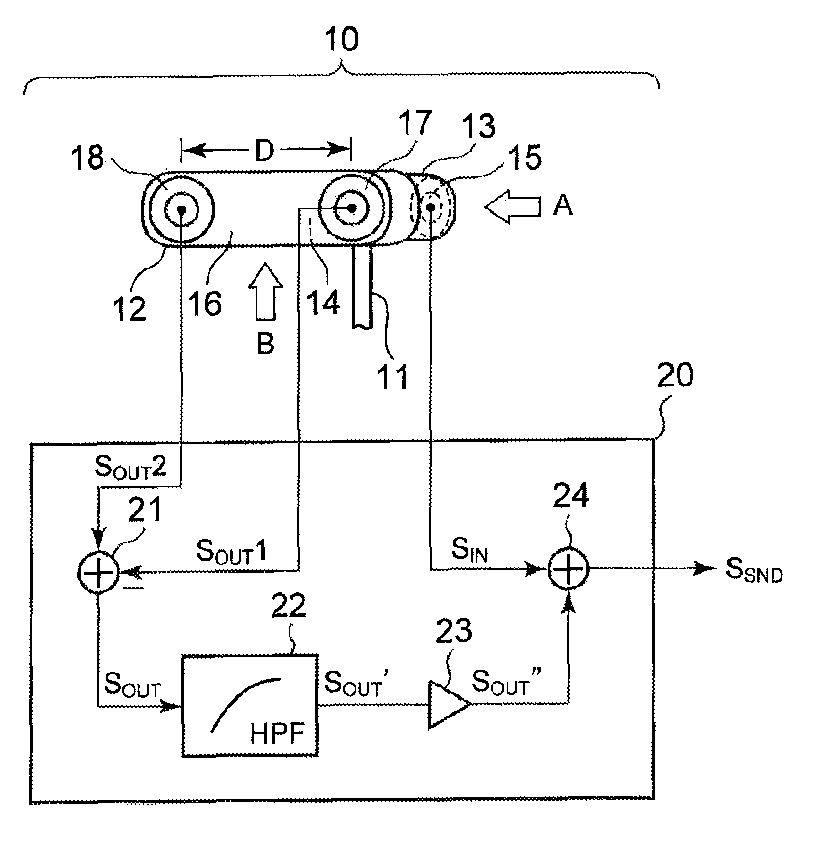
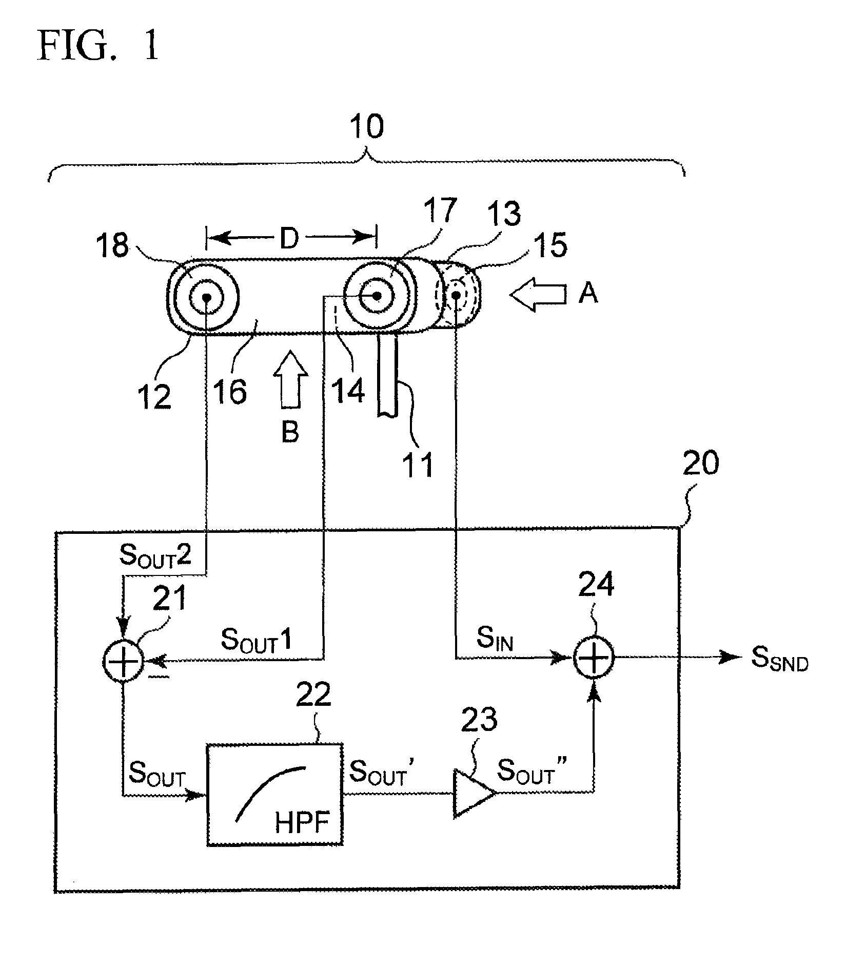
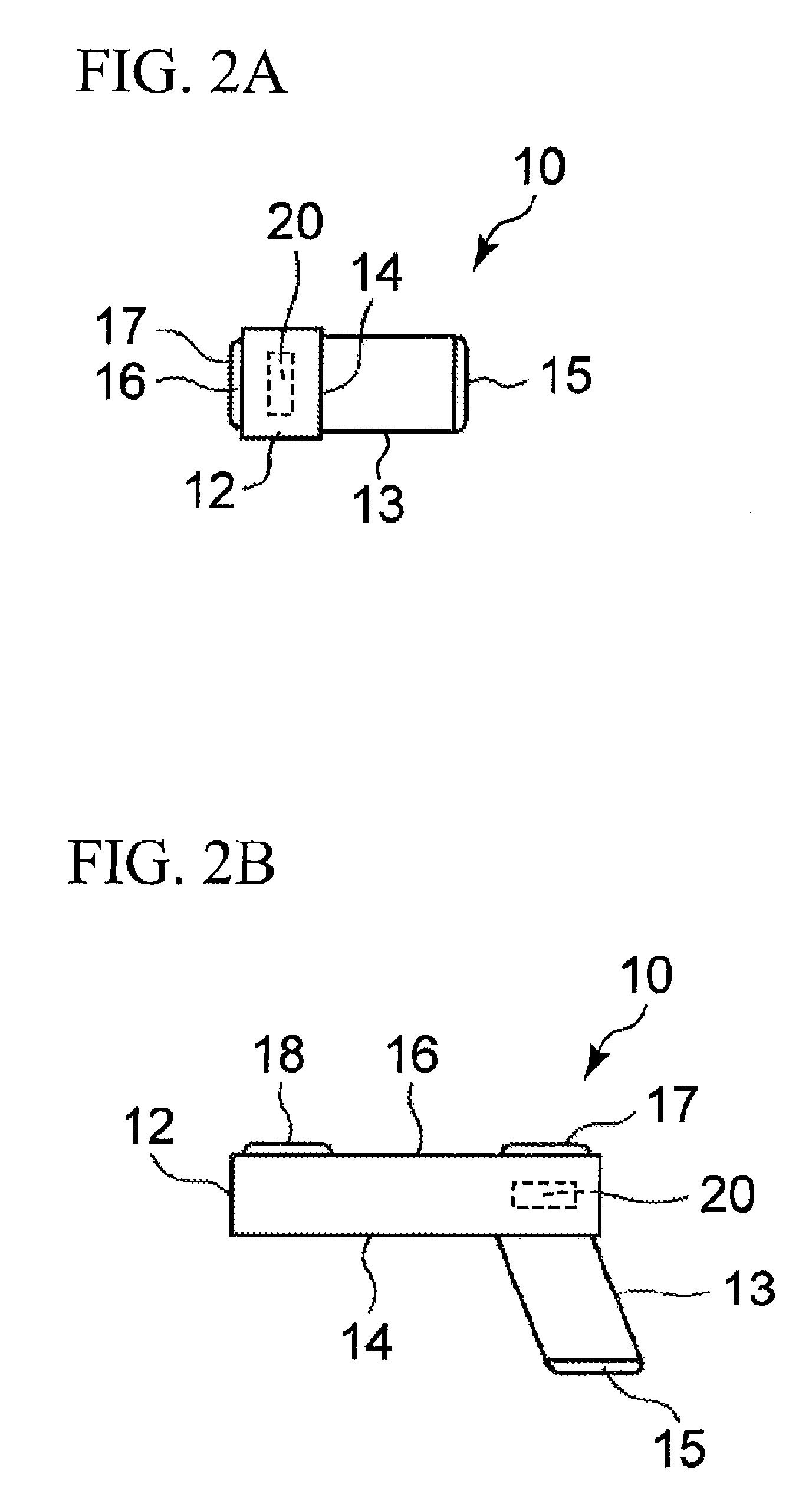
[0024]FIG. 1 shows the mechanical / electrical constitution of an earphone microphone 10 according to a first embodiment of the present invention. FIG. 2A is a front view of the earphone microphone 10 observed in a direction A in FIG. 1, whilst FIG. 2B is a side view of the earphone microphone 10 observed in a direction B in FIG. 1.

[0025]The earphone microphone 10 inputs a received sound signal SRCV from a mobile phone (or a cellular phone, not shown) via a cable 11 so as to output (or emit) a corresponding sound into an external auditory canal of a user's ear. In addition, the earphone microphone 10 receives both of an internal sound which is produced by a vocal cord and transmitted into an external auditory canal via a skull and an external sound which is output from a mouth and transmitted into an external auditory canal via an external space. The internal sound transmitted into an external auditory canal via a skull has a frequency range lower than 3 kHz. The ea...

second embodiment

2. Second Embodiment

[0047]FIG. 6 shows the mechanical / electrical constitution of an earphone microphone 10A according to a second embodiment of the present invention, wherein parts identical to those shown in FIG. 1 are designated by the same reference numerals. Compared to the earphone microphone 10 of the first embodiment in which two receivers 17, 18 are disposed on the external surface 16 of the main unit 12, the earphone microphone 10A of the second embodiment is equipped with one receiver 17 which is configured of a unidirectional microphone disposed on the external surface 16 of the main unit 12. In the earphone microphone 10A, the receiver 17 receives an external sound so as to generate a sound signal SOUT, which is supplied to the HPF 22. The HPF 22 attenuates low frequency components lower than 3 kHz in the sound signal SOUT, thus producing a sound signal SOUT′ including frequency components higher than 3 kHz. The sound signal SOUT′ is amplified in the amplifier 23, which ...


PUM


Abstract

An earphone microphone is constituted of a main unit and an insert portion which are united in an L-shape. Two receivers are attached to the external surface of the main unit and exposed externally of a user's ear, while one receiver is attached to a distal end of the insert portion that is inserted into a user's external auditory canal and disposed opposite to a user's eardrum. A signal processor produces a difference signal between the output signals of two receivers exposed externally of the user's ear. The difference signal is subjected to high-pass filtering and subsequently added to the output signal of the receiver disposed inside the user's external auditory canal, thus producing a sound signal representing a user's sound. The sound signal includes a sufficient number of frequency components (e.g. frequency components higher than 3 kHz) prerequisite for discriminating the user's sound.

Description

BACKGROUND OF THE INVENTION[0001]1. Field of the Invention[0002]The present invention relates to electroacoustic receivers / transmitters, and in particularly to earphones / microphones that receive and transmit sounds.[0003]The present application claims priority on Japanese Patent Application Nos. 2010-39296 and 2010-263676, the content of which is incorporated herein by reference.[0004]2. Description of the Related Art[0005]Earphones / microphones (or earphone microphones) have been developed and widely used as optional devices of mobile phones (or cellular phones) allowing users to conduct hand-free conversations with counterpart ones. Earphone microphones can be designed such that miniature microphones are embedded in earpieces inserted into external auditory canals of users' ears, wherein miniature microphones receive sounds transmitted inside external auditory canals via skulls (see Patent Document 1). When earpieces are inserted into external auditory canals so as to close externa...

Claims


Application Information

Patent Timeline
Patent Type & Authority Patents(United States)
IPC IPC(8): H04R25/00
CPCH04R3/005H04R1/083H04R1/1083H04R2201/107
Inventor YATAKA, KOJI
Owner YAMAHA CORP
Learn More