
Removal of surface-wave noise in seismic data

a seismic data and surface wave noise technology, applied in seismology, instruments, borehole/well accessories, etc., can solve the problems of limiting the ability to use seismic data for determining, affecting the ability to use seismic data for assessing the hydrocarbon potential of prospective reservoirs, and limiting the ability to optimize the well placement for extraction of hydrocarbons

Active Publication Date: 2013-10-08
EXXONMOBIL UPSTREAM RES CO
View PDF27 Cites 14 Cited by
  • Summary
  • Abstract
  • Description
  • Claims
  • Application Information

AI Technical Summary

Problems solved by technology

Unfortunately, there is not a single characteristic that uniquely distinguishes surface waves and reflections, and such filters remove some reflection signal along with the noise.
In addition, the performance of signal-processing filters degrades when the behaviors of the surface-waves are complex and change laterally over the survey area and when the distances between receivers are too long or too irregular as is typically found with 3D seismic surveys.
The effect of removing part of the reflections or leaving residual noise is to limit the ability to use the seismic data for determining the detailed physical structure and properties of a subsurface earth region.
In particular, the ability to use the data for assessing the hydrocarbon potential of a prospective reservoir and for optimizing the well placement for extraction of the hydrocarbons is limited.
One of the common problems from inadequate surface-wave removal is the lack of good amplitude fidelity of the processed seismic data.
For the later, surface wave noise can mask the reflection amplitudes and conventional processing methods cannot remove the noise without adversely affecting the integrity of amplitudes of the reflections.
Sophisticated AVO inversion methods for reservoir property estimation, in particular, need high-integrity low-frequency reflection amplitudes at different source- and receiver offset distances (reflection angles) and are particularly affected by poorly mitigated surface wave noise.
Unfortunately, the low-frequency components of the reflections are also removed, and along with them, the ability for deep imaging and for sophisticated reservoir property analyses.
However, the success of polarization filtering for seismic imaging applications is limited because the surface-wave energy does not consist of only simple Rayleigh waves but rather a mix of Rayleigh waves and other higher-order, faster modes of surface waves that do not have distinctive polarization characteristics compared to signal.
Such interference makes the computation of polarization ambiguous and limits the ability to remove surface waves and retain reflections.
A problem with such methods is that they require a sufficiently short distance between each of the receivers so that the recorded ground roll is not aliased, i.e. so that the ground roll is adequately sampled.
Additional problems arise with multi-trace velocity filters because of the complexity and variability of the near-surface and surface-wave behaviors.
With broader filters or multiple passes, more reflection energy can be harmed.
Furthermore because of attenuation, the ground-roll amplitude is decreasing rapidly with larger source to receiver distances, and the multi-trace filter performance is reduced.
Finally, the properties of the near-surface and thus the velocities of the ground roll can change laterally requiring changing filter parameters and limiting the effectiveness of the filters.
Such velocity changes can be difficult to estimate, because two-dimensional transforms, such as ƒ-k transforms or radon transforms, effectively average over all of the receiver traces in the gather.
The primary assumption and limitation in the Ernst tomographic method is that it must use a time window with only one ground-roll mode.
When these conditions are not met, the amplitude (dynamic) part of the wavefield will not be correct.
Another part of the limitation are the requirements for source locations such as on a perimeter of the survey or so that they are at points of stationary phase for the surface waves but not for reflectors.
There are a number of issues with this method that have not been resolved, particularly with 3D data.

Method used


Image

  • Removal of surface-wave noise in seismic data
  • Removal of surface-wave noise in seismic data
  • Removal of surface-wave noise in seismic data

Examples


examples

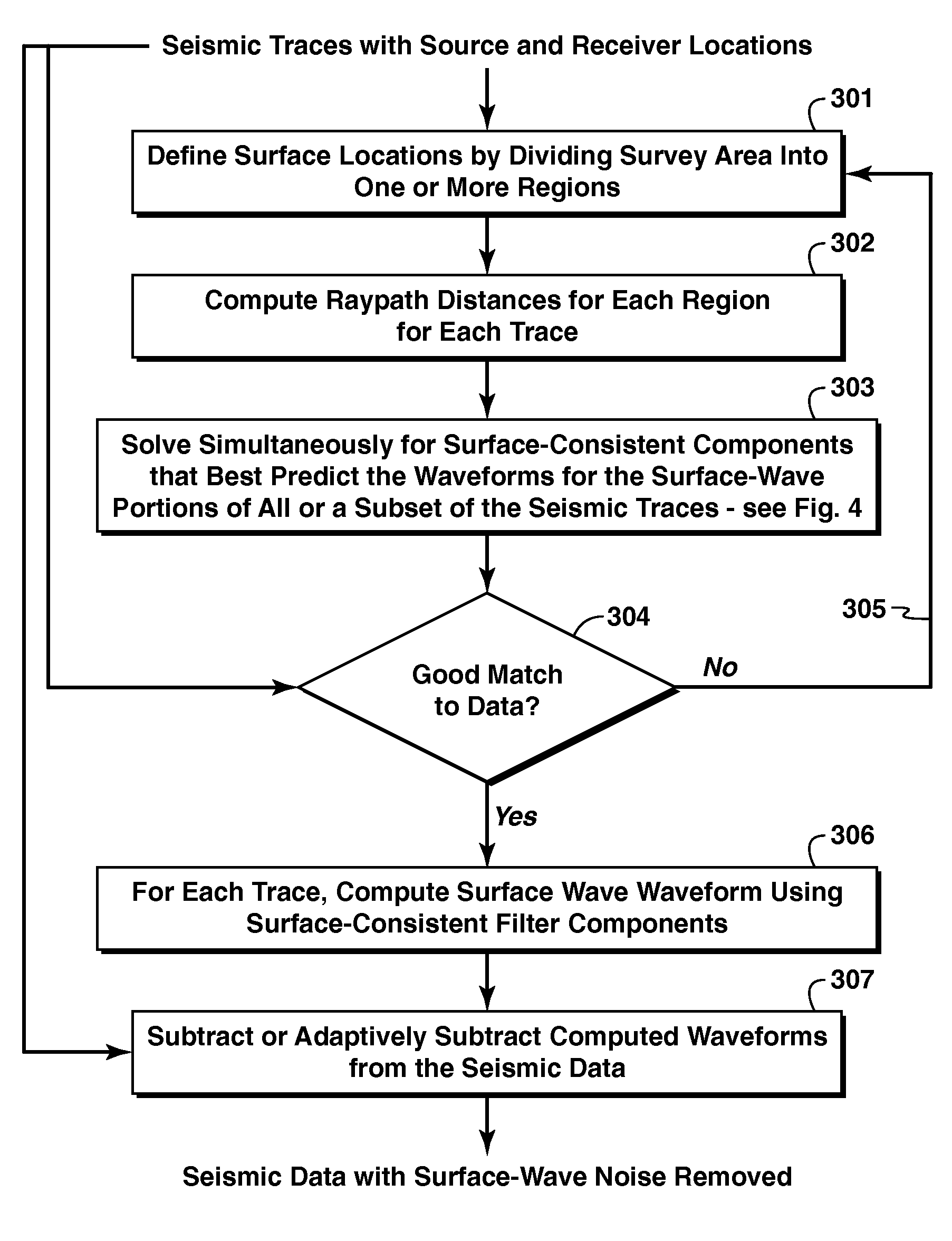
[0088]A couple of examples of the estimation of ground-roll waveforms are shown here. These are examples for computer simulated data using a full 3D viscoelastic wave-equation solution for flat layers. The simulation was performed with a 20-Hz Ricker source wavelet. Because the model is of flat layers, there is no lateral variation in soil types, so there is only one region. Also, there are no receiver coupling variations. In these simple examples, the parameterization reduces to two components: the source and propagation terms for each mode.

[0089]The first example is a single 5-m thin layer over a half space. There is only one surface-wave mode, which is dispersive, as shown in FIG. 6 for four source to receiver distances (offset) ranging from 500 m (61) to 2,000 m (62) in uniform increments of 500 m. These represent a few traces from the seismic data input for step 301. The outputs of the model optimization step 303 are shown in FIGS. 7A-D. These include the source partition ampli...


PUM


Abstract

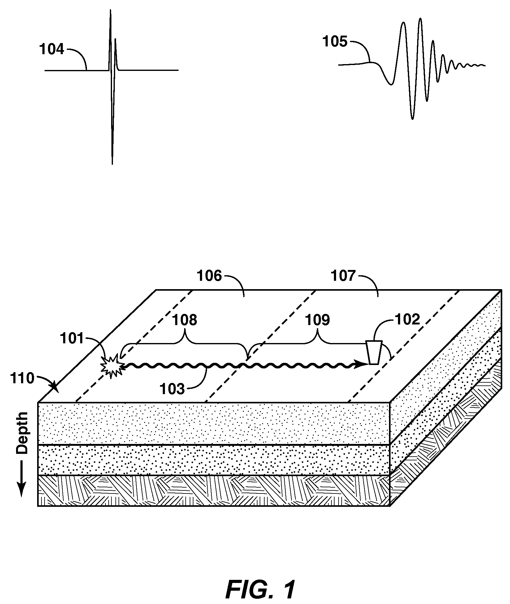
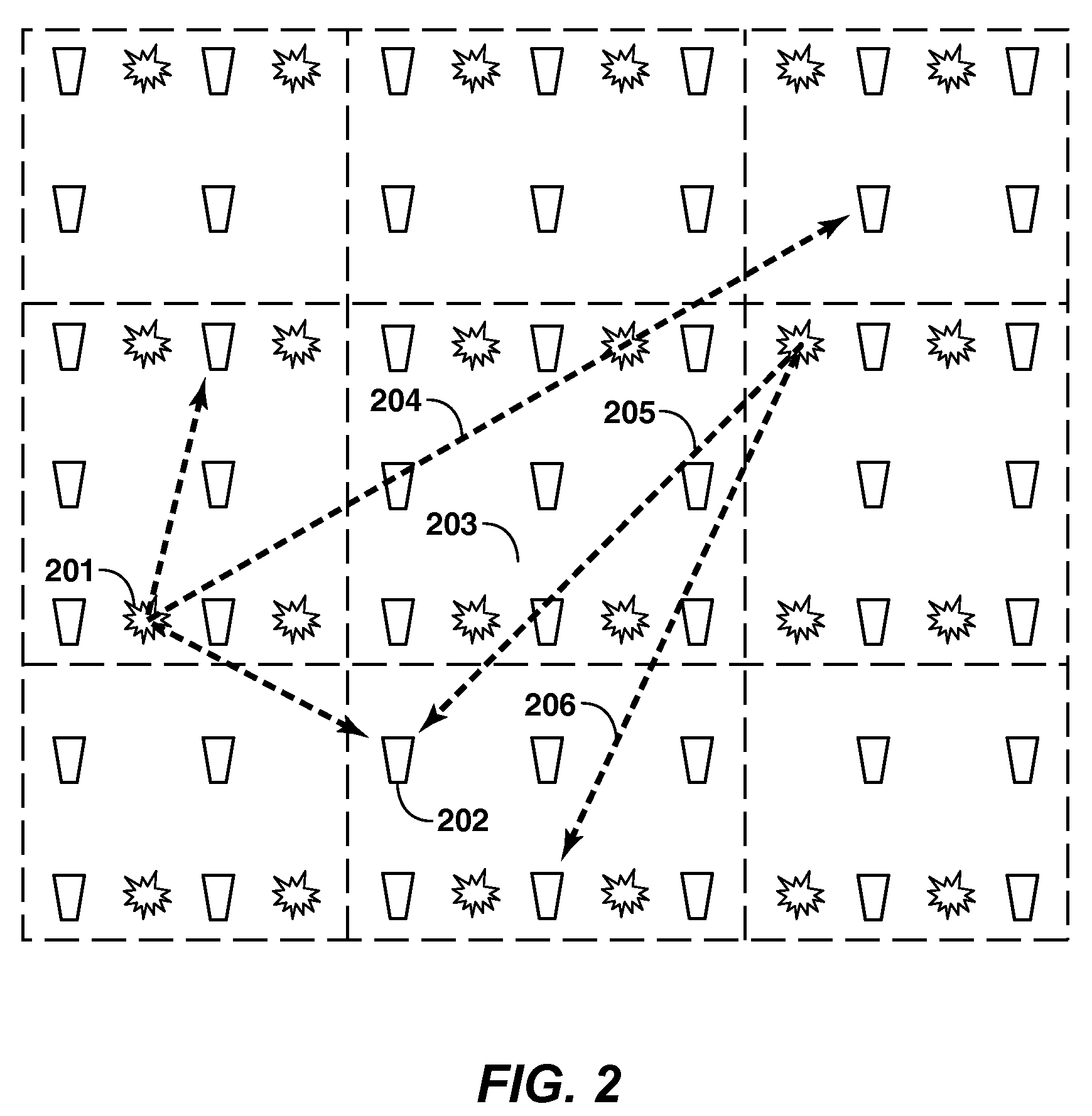
The invention is a method to predict surface-wave waveforms (306) and subtract them (307) from seismic data. Prediction is done by estimating a set of surface-consistent components (transfer functions in the frequency domain or impulse responses in time domain) that best represent changes in the waveforms for propagation along the surface from source to receiver (303). The prediction uses a mathematical expression, or model, of the earth's filtering effects, both amplitude and phase, as a function of frequency. The desired surface-consistent components are model parameters, and model optimization is used to solve for the surface-consistent components. The surface-consistent components may include filter transfer functions for each source location, each receiver location, and for propagation (302) through each region (301) of the surface that exhibits lateral variation.

Description

CROSS REFERENCE TO RELATED APPLICATIONS[0001]This application is the National Stage entry under 35 U.S.C. 371 of PCT / US2009 / 048003 that published as WO 2010 / 019314 and was filed on 19 Jun. 2009, which claims the benefit of U.S. Provisional Application No. 61 / 087,938, filed on 11 Aug. 2008, each of which is incorporated by reference, in its entirety, for all purposes.FIELD OF THE INVENTION[0002]This invention relates generally to the field of seismic prospecting and, more particularly to seismic data processing. Specifically, the invention is a method for using seismic data to predict the waveforms for surface-wave noise and then subtracting them from the seismic data where they overlie the deep reflected returns and constitute noise when the data are processed for determining the physical structure or a physical property of a subsurface earth region.BACKGROUND OF THE INVENTION[0003]Seismic data recorded for the purpose of imaging subsurface reflections are contaminated by seismic wa...

Claims


Application Information

Patent Timeline
Patent Type & Authority Patents(United States)
IPC IPC(8): G01V1/00
CPCG01V1/364G01V1/00G01V2210/20G01V2210/32G01V2210/3246
Inventor KROHN, CHRISTINE E.
Owner EXXONMOBIL UPSTREAM RES CO
Learn More