Eureka AIR delivers breakthrough ideas for toughest innovation challenges, trusted by R&D personnel around the world.

Implantable zero-wire communications system

a zero-wire communication and wireless communication technology, applied in the field of medical devices and methods, can solve the problems of impracticality for many applications and the lower bound of the device size, and achieve the effect of effective wireless communication

Active Publication Date: 2013-10-01
OTSUKA PHARM CO LTD
View PDF958 Cites 162 Cited by
  • Summary
  • Abstract
  • Description
  • Claims
  • Application Information

AI Technical Summary

Benefits of technology

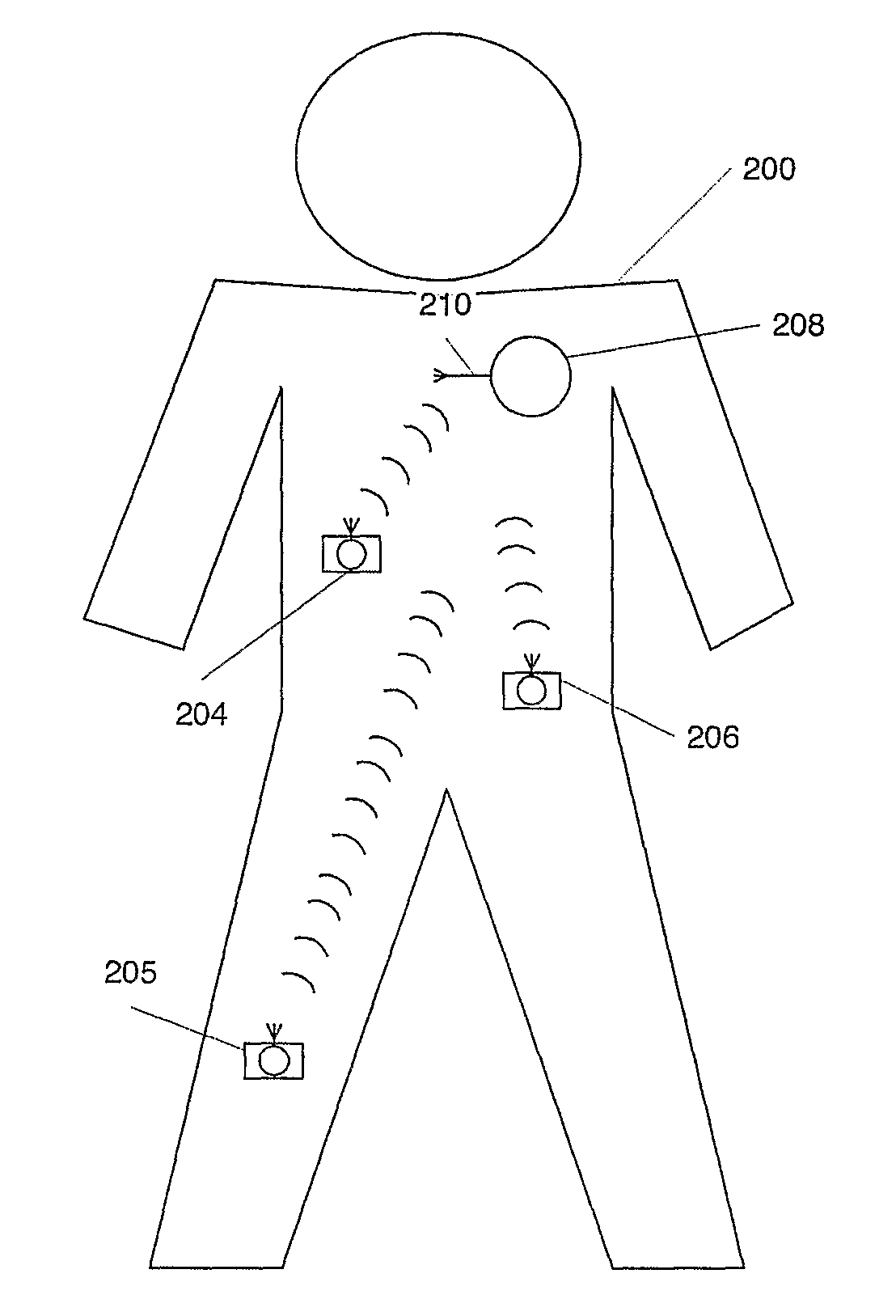
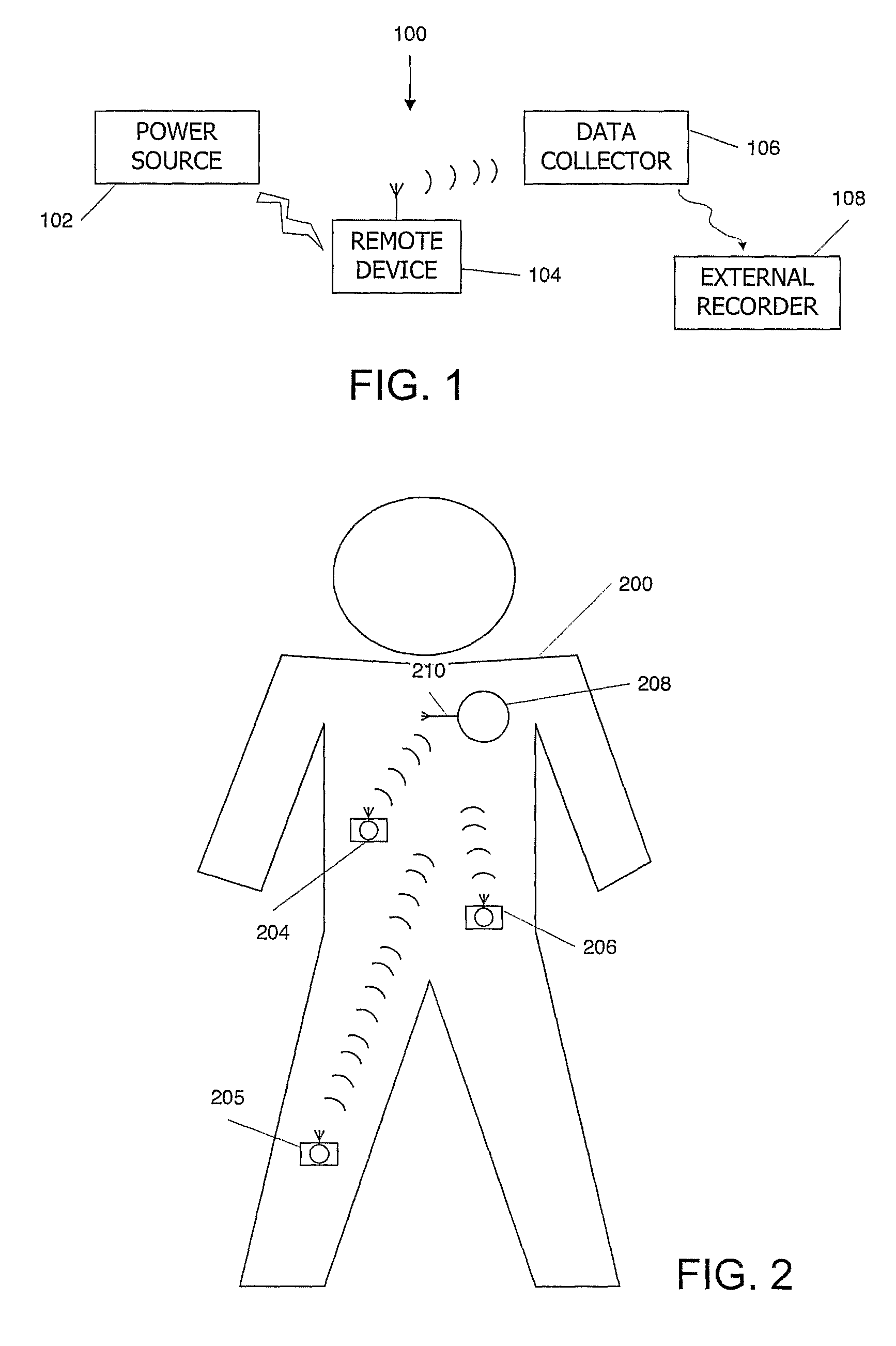
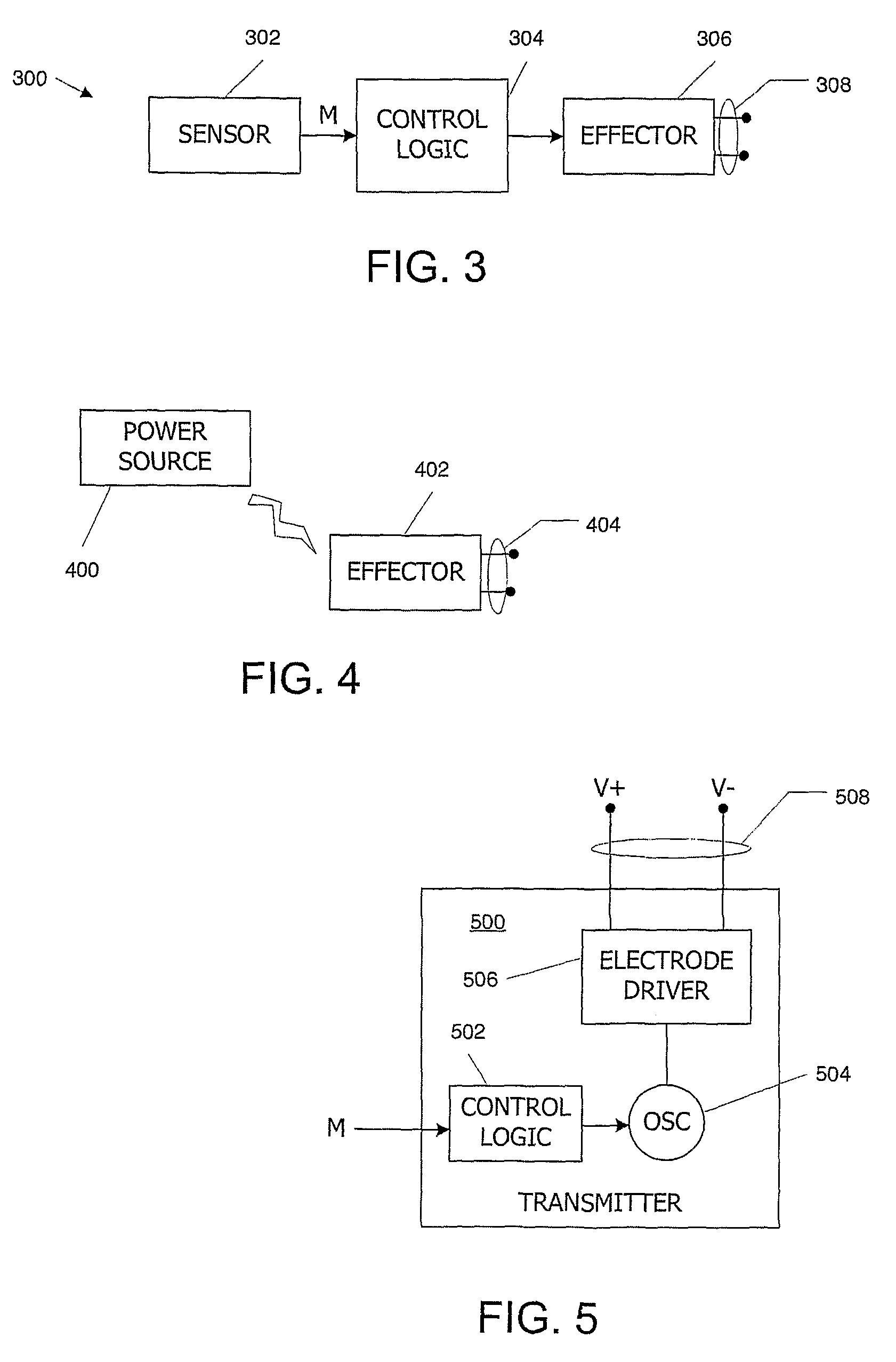
[0010]The present invention allows, for the first time, an implantable system that can be made up of conveniently small communications devices which nonetheless effectively communicate with each other in the body. Accordingly, an implantable communications platform is provided which is amenable to a multitude of different applications, including both diagnostic and therapeutic applications. The small size of the individual components of the system in accordance with embodiments of the invention and the ability of the components to effectively communicate wirelessly with each other through the body enables a number of different applications not heretofore possible.

Problems solved by technology

These requirements place a lower bound on the size of the devices, making them impractical for many applications.

Method used


Image

  • Implantable zero-wire communications system
  • Implantable zero-wire communications system
  • Implantable zero-wire communications system

Examples


example

Blood Flow in Vena Cava

[0292]An experiment was performed using a blood flow sensor of the type described herein. The experimental setup and results are presented by way of illustrating the efficacy of an embodiment of the present invention, and this description is not intended to limit the scope of the claims.

[0293]Resistivity blood flow sensors as described above were employed. Using a pig as the test subject, one sensor (with a pair of electrodes) was placed in the superior vena cava (SVC) and another in the inferior vena cava (IVC), and a two-point measurement was performed. Constant voltage was applied between each pair of electrodes, and the voltage across a 10-ohm resistor in series was measured. The measured voltage is proportional to current and thus inversely proportional to impedance between the two electrodes in the pair.

[0294]FIGS. 14A and 14B are results obtained from experiments in an anesthetized pig. The top panel (S1) corresponds to the SVC, and the second panel (S2...


PUM


Abstract

The present invention provides implantable systems that communicate wirelessly with each other using a unique format that enables devices configurations and applications heretofore not possible. Embodiments of the present invention provide communication apparatuses and methods for exchanging information with implantable medical devices. In some embodiments, two implantable devices communicate with each other using quasi-electrostatic signal transmission in a long wavelength / low frequency electromagnetic band, with the patient's body acting as a conductive medium.

Description

CROSS-REFERENCE TO RELATED APPLICATIONS[0001]Pursuant to 35 U.S.C. §119 (e), this application claims priority to the filing date of: U.S. Provisional Patent Application Ser. No. 60 / 713,881 filed Sep. 1, 2005; U.S. Provisional Patent Application Ser. No. 60 / 713,680 filed Sep. 1, 2005 and U.S. Provisional Patent Application Ser. No. 60 / 739,174 filed Nov. 23, 2005; the disclosures of which applications are herein incorporated by reference.INTRODUCTION[0002]1. Field of the Invention[0003]The present invention relates to medical apparatuses and methods, and in particular to methods and apparatuses for communicating information wirelessly within an organism, such as a patient.[0004]2. Background of the Invention[0005]Pacemakers and other implantable medical devices find wide-spread use in today's health care system. A typical pacemaker includes stimulating electrodes that are placed in contact with heart muscle, detection electrodes placed to detect movement of the heart muscle, and contr...

Claims


Application Information

Patent Timeline
Patent Type & Authority Patents(United States)
IPC IPC(8): G08C17/00
CPCA61B5/0028A61B5/0031A61B5/0265A61B5/14535A61B5/415A61B5/418A61B5/6862A61B5/6876A61N1/37223A61B5/0022A61B5/026A61M5/172A61N1/37217A61B5/01A61B5/0215A61B5/145H02J50/20Y02A90/10H02J2310/23
Inventor ZDEBLICK, MARK J.ROBERTSON, TIMOTHY
Owner OTSUKA PHARM CO LTD
Why Eureka
Eureka Blog
Learn More