
Electrical connector with improved mating means

a technology of electrical connectors and mating means, applied in the direction of coupling device connections, coupling protective earth/shielding arrangements, electric discharge lamps, etc., can solve the problems of hdmi and displayport appearance differences, conventional art fails to provide a position function in a simple way, and tongue damage risk

Active Publication Date: 2013-09-17
CHANT SINCERE CO LTD
View PDF4 Cites 35 Cited by
  • Summary
  • Abstract
  • Description
  • Claims
  • Application Information

AI Technical Summary

Benefits of technology

The solution allows for safe and efficient insertion of both HDMI and DisplayPort plugs into a single connector, preventing damage and ensuring proper connection by using a detect pin to differentiate plug types and guide their insertion.

Problems solved by technology

The width dimensions of these two were usually different resulted in the appearance differences between HDMI and DisplayPort.
Though such connector decreases size and still adopts only single port that seems a great idea to miniaturize connector, however, a problem occurs wherein conventional art uses a tongue portion in order to guide the plug.
In condition of HDMI plug having a small size than DisplayPort plug, conventional art fails to provide a position function in a simple way.
So failures always happen during plugging and worsen to the risk of tongue-damaging, even the risk of housing-damaging, as users are trying to accurately position the plug.
Looking into many other mating means, such plug connector fails to provide an efficient detecting / guiding mechanism to identify two plugs.
Such drawback obviously is a potential risk to the device makers, at the time that devastated quality issue from adopted parts is not allowed, or otherwise it is eventually being harmful to selling products.

Method used


Image

  • Electrical connector with improved mating means
  • Electrical connector with improved mating means
  • Electrical connector with improved mating means

Examples


Embodiment Construction

)

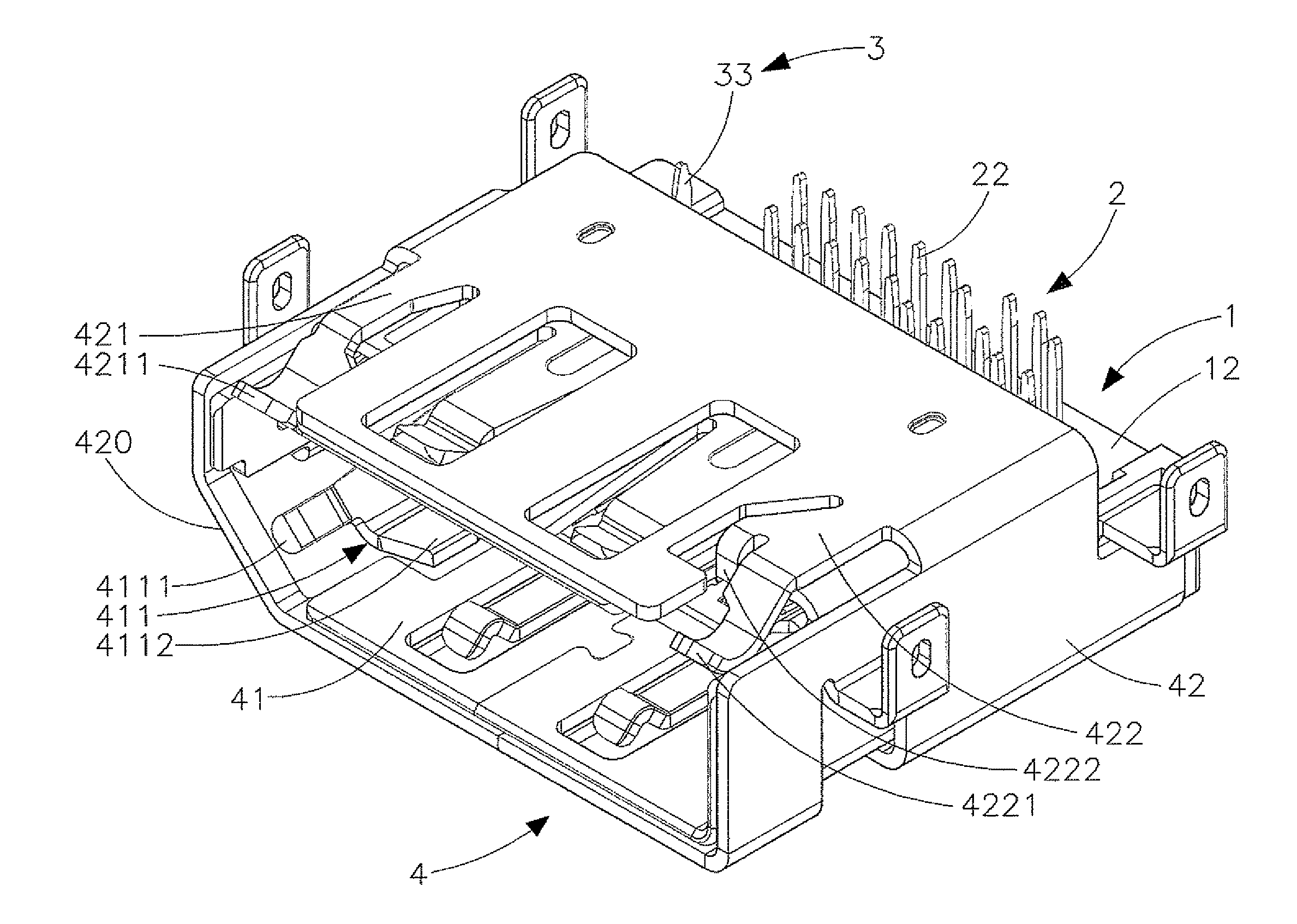
[0026]As shown in FIGS. 1-3, the present embodiment is illustrated in a perspective view and exploded perspective views. An electrical connector comprises: an insulative housing 1, a plurality of terminals 2, a detect pin 3 and a shell assembly 4.

[0027]The insulative housing 1 consists of a terminal seat 11 and a block 12. Terminal seat 11 extended forwardly from a base portion 111 configures a tongue 112, wherein recessions 1121 are provided at both top and bottom sides of tongue 112. Terminal seat 11 extended backwardly from base portion 111 configures two extension portions 113 wherein each extension portion 113 contains an aperture 1131 at inner side. Block 12 consists of holes 121 on surface and tabs 122 which configure to engage with apertures 1131.

[0028]A plurality of terminals 2 is installed in terminal seat 11 wherein each terminal has a contact end 21 disposed in the recession 1121 and a soldering tail 22 passing through the hole 121 of block 12. A plurality of terminals ...


PUM


Abstract

An electrical connector comprising an insulative housing, a plurality of terminals, a detect pin and a shell, includes a insulative housing having a terminal seat extending forwardly from a base portion and configuring a tongue, and defining a receiving room between bottom of the tongue and a shell, and a plurality of terminals installed in the terminal seat containing nineteen pins compacting to transmit HDMI signals and with one plus pin compacting to transmit DisplayPort signals, and a shell accommodating the insulative housing and including a first engagement portion, a second engagement portion, and a third engagement portion.

Description

BACKGROUND OF THE INVENTION[0001]1. Field of the Invention[0002]The present invention relates generally to an electrical connector, and more specifically, to an electrical connector that improving the mating means thereof, wherein providing a solution to insert different type plugs into identical connector free from destructing itself.[0003]2. Description of the Related Art[0004]Technologies today have been transformed rapidly. They are utilized approximately in all social sectors and closely connect with people's life. Communication technology applied in those computer-peripheral devices generally uses transmission cables to up / download with mass data. The plug assembled with a cable, which is predetermined to be inserted into a socket on a device, thus plays a role as being a key element in communication technology.[0005]By year to year, since markets replaced and products retired, the following standards “High Definition Multimedia Interface”, abbreviated as “HDMI” promoted by HD...

Claims


Application Information

Patent Timeline
Patent Type & Authority Patents(United States)
IPC IPC(8): H01R24/00
CPCH01R12/724H01R13/6594
Inventor YEN, MING HUICHOU, CHUN CHI
Owner CHANT SINCERE CO LTD
Learn More