Bladeless air fan

a bladeless air fan and blade technology, applied in the direction of positive displacement liquid engine, piston pump, valve construction, etc., can solve the problems of inability to prevent small objects, small children could poke fingers in the gaps of the frame inadvertently and be injured, and the frame still has gaps, so as to increase the range of rotation of the air discharging portion, enhance airflow convergence, and increase the airflow speed

Inactive Publication Date: 2013-09-10
KABLE ENTERPRISE
View PDF9 Cites 52 Cited by
  • Summary
  • Abstract
  • Description
  • Claims
  • Application Information

AI Technical Summary

Benefits of technology

[0009]By means of the features set forth above, the air discharging portion can be rotated beyond the housing space of the host without being hindered, thus increasing the range of the rotation of the air discharging portion.
[0010]Moreover, the air discharging portion includes an airflow gathering wall, and an inner ring compression wall and an outer ring compression wall extended forwards from two ends of the airflow gathering wall. From the junctions of the airflow gathering wall and inner ring compression wall and outer ring compression wall, the inner ring compression wall and outer ring compression wall are spaced from each other at a gradually decreasing distance between them, and the inner ring compression wall and outer ring compression wall also have distal ends by a gap to form a front air outlet to discharge airflow forwards. Such a design can increase airflow speed and enhance airflow convergence.

Problems solved by technology

But the frame still has gaps and small children could poke fingers inadvertently through the gaps of the frame and be injured by the high speed spinning blades.
The frame also cannot prevent small articles from piercing through, hence small children could also insert incidentally playing articles into the frame to damage the articles or the blades.
Moreover, the frame cannot prevent dust from accumulating on the blades.
Unless the fan is washed and cleaned frequently the spinning blades could throw a great amount of dust outside to cause allergic implications on respiratory organs and skin of people after a prolonged period of time, or even inflict ailments.
However, its air outlet is located at the inner rear side of the air discharging portion and formed in a tortuous manner, airflow resistance passing through the air outlet increases and results in decrease of airflow power.
The bladeless air fan is more expensive but does not provide desirable performance, hence is not well accepted on the market.
It also has the drawback of inadequate airflow amount like the previous reference.
In the reference of M394383, with the air inlets and outlets located on the inner rim of the frame, the problem of inadequate airflow power also is unavoidable.
While it has the advantage of balanced airflow because of the Coanda effect, the shifted airflow also generates resistance to the airflow and results in lower airflow exit speed.
In short, the aforesaid conventional techniques have the airflow generator located below the frame and result in constraint of frame swiveling.
The conventional air discharge design also does not produce sufficient airflow power.

Method used


Image

  • Bladeless air fan
  • Bladeless air fan
  • Bladeless air fan

Examples


Embodiment Construction

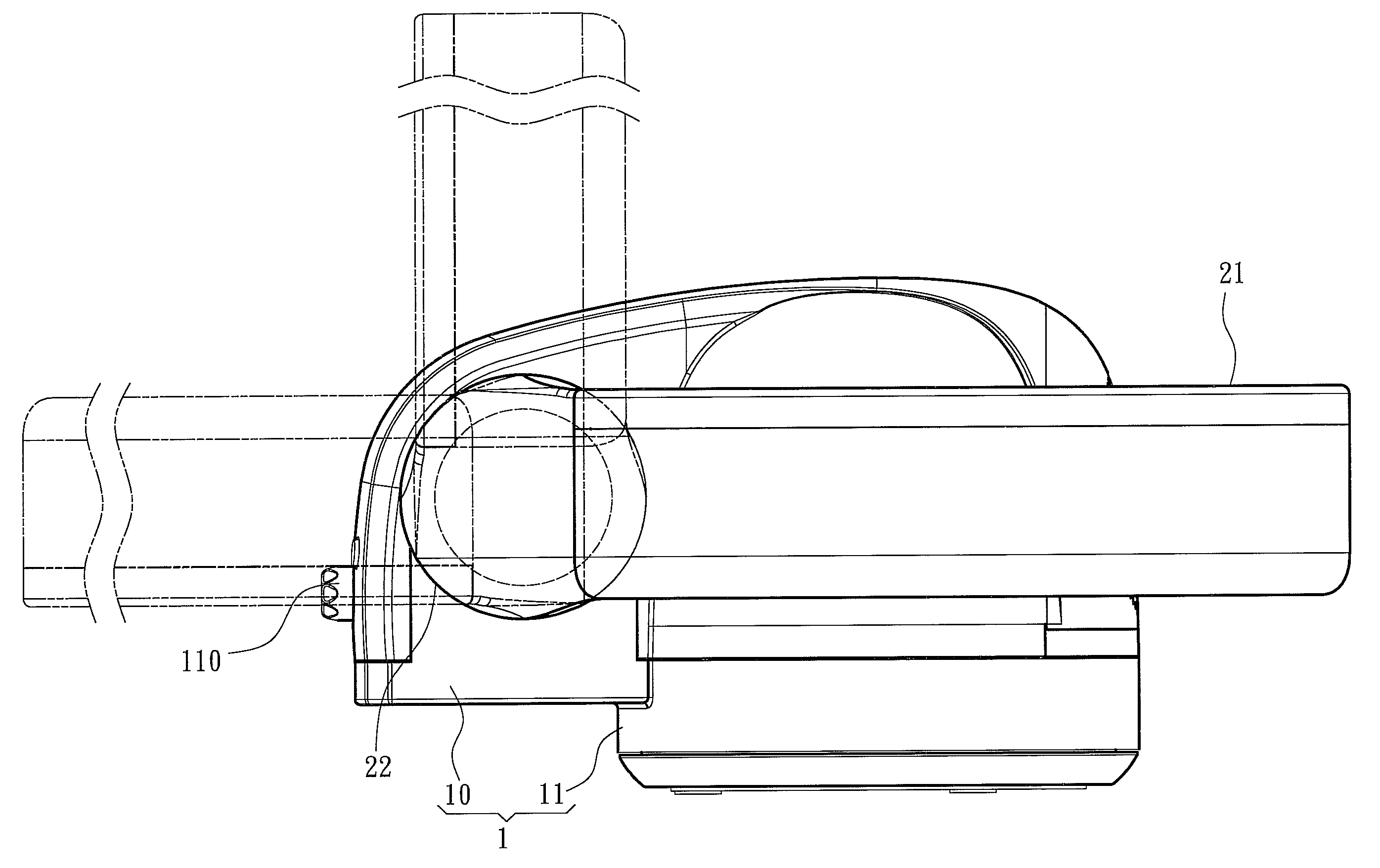
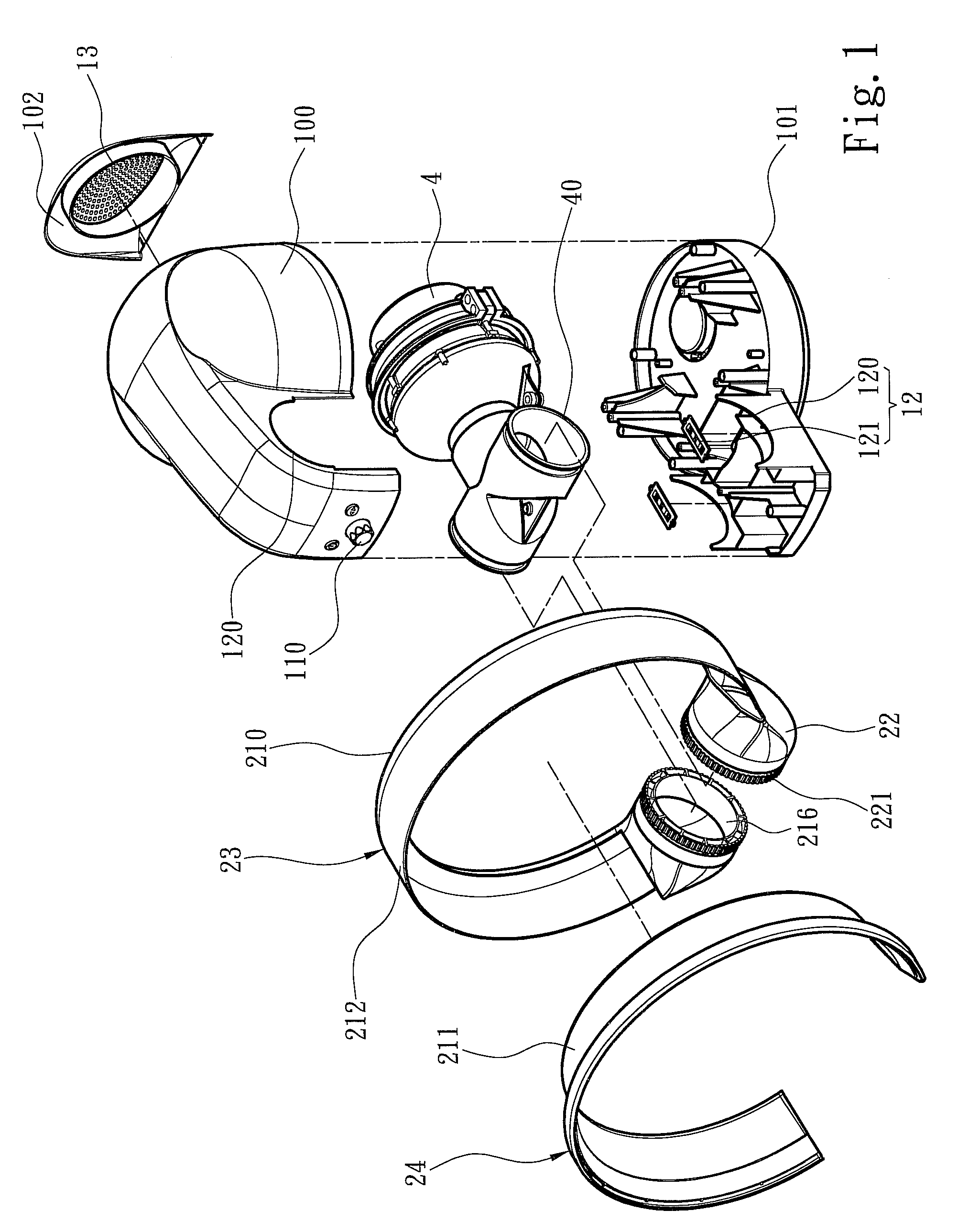
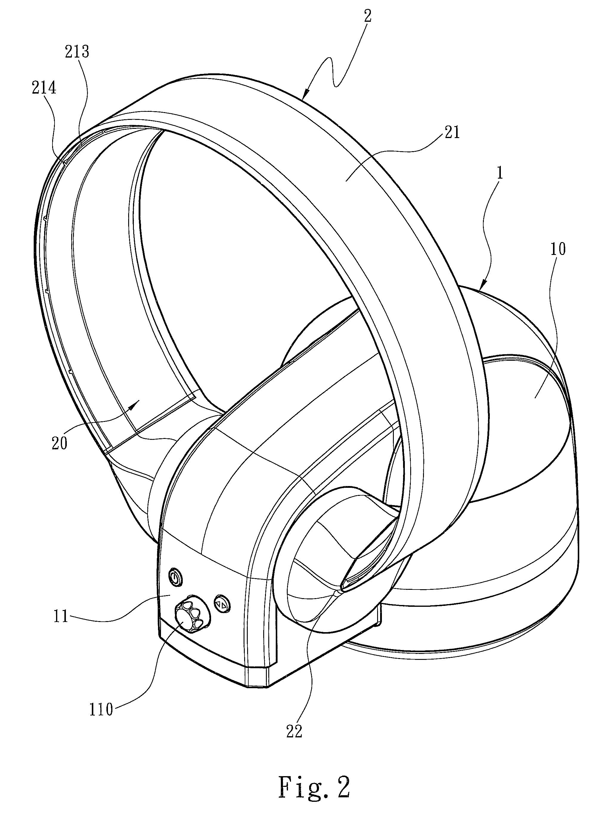
[0019]Please referring to FIGS. 1 and 2, the present invention aims to provide a bladeless air fan. The bladeless air fan includes a host 1 and an airflow guiding frame 2. FIG. 1 shows an embodiment in which the host 1 includes an upper case 100, a lower case 101 and a rear case 102. The embodiment shown in FIGS. 1 and 2 is merely a preferable structural embodiment of the host 1 and not the limitation thereof. Modifications of the cases and profiles can be made easily by those skilled in the art and shall be included in the scope of this invention. The host 1 is divided into a housing section 10 and a pivoting section 11 extending from the housing section to hold an airflow guiding manifold 40. The housing section 10 holds an airflow generator 4 connecting to the airflow guiding manifold 40. The airflow guiding manifold 40 is extended from the housing section 10 to the pivoting section 11. The rear case 102 has a plurality of air inlets 13 formed at one side of the airflow generator...


PUM


Abstract

A bladeless air fan includes a host and an airflow guiding frame. The host divides into a housing section to hold an airflow generator and a pivoting section to include two first pivoting portions. The airflow generator is connected to an airflow guiding manifold extended from the housing section to the pivoting section. The airflow guiding frame includes an air discharging portion and an airflow guiding passage and two second pivoting portions being annular to form two air intake ports communicating with the airflow guiding passage. The second pivoting portions are rotatably coupled with the first pivoting portions such that the airflow guiding passage communicates with the airflow guiding manifold. The air discharging portion encircles an airflow passage being formed at an inner diameter allowing the housing section to pass through to enlarge the range of the second pivoting portions rotating against the first pivoting portions.

Description

FIELD OF THE INVENTION[0001]The present invention relates to a bladeless air fan and particularly to a bladeless air fan that has an improved air discharge structure to realize a greater air discharge rotational angle and improve air delivery.BACKGROUND OF THE INVENTION[0002]An air fan relies on spinning blades to pressurize air to generate airflow. A conventional air fan has exposed blades driven by a motor to get spinning and a mesh type frame to surround the blades to avoid hurting people. But the frame still has gaps and small children could poke fingers inadvertently through the gaps of the frame and be injured by the high speed spinning blades. The frame also cannot prevent small articles from piercing through, hence small children could also insert incidentally playing articles into the frame to damage the articles or the blades. Moreover, the frame cannot prevent dust from accumulating on the blades. Unless the fan is washed and cleaned frequently the spinning blades could t...

Claims


Application Information

Patent Timeline
Patent Type & Authority Patents(United States)
IPC IPC(8): F15D1/00
CPCF04D25/08F04F5/16Y10T137/206
Inventor LI, DE-ZHENG
Owner KABLE ENTERPRISE
Why Eureka
Try Eureka