
Control apparatus of driving force in case of belt slipping for vehicle equipped with V-belt continuously variable transmission and control method thereof

a technology of control apparatus and transmission, which is applied in the direction of mechanical apparatus, digital data processing details, instruments, etc., can solve the problems of changing the driving force, and achieve the effect of reducing the deterioration of the vehicle running performance or the uncomfortable feeling

Inactive Publication Date: 2013-09-03
NISSAN MOTOR CO LTD +1
View PDF11 Cites 3 Cited by
  • Summary
  • Abstract
  • Description
  • Claims
  • Application Information

AI Technical Summary

Benefits of technology

The patent aims to prevent a decrease in the vehicle's driving force during belt slipping control in a V-belt continuously variable transmission. This helps to maintain the vehicle's performance and comfort.

Problems solved by technology

In the V-belt continuously variable transmission equipped with the belt slip control apparatus, when shift control is performed such that the pulley rotation ratio reaches the value corresponding to the target speed ratio (the target input rotation speed), as described above, such a problem as described below occurs.
In this case, even if shift control is performed such that the pulley rotation ratio reaches the value corresponding to the target speed ratio under the same transmission input torque, a transmission output torque (a driving force of the vehicle) varies by an amount corresponding to variation (offset) of the relationship between the pulley rotation ratio and the torque amplifying ratio, which results in such a problem that the driving force is changed due to control of belt slip.

Method used


Image

  • Control apparatus of driving force in case of belt slipping for vehicle equipped with V-belt continuously variable transmission and control method thereof
  • Control apparatus of driving force in case of belt slipping for vehicle equipped with V-belt continuously variable transmission and control method thereof
  • Control apparatus of driving force in case of belt slipping for vehicle equipped with V-belt continuously variable transmission and control method thereof

Examples


Embodiment Construction

[0031]Embodiments of the present invention will be explained below with reference to the drawings.

[0032]

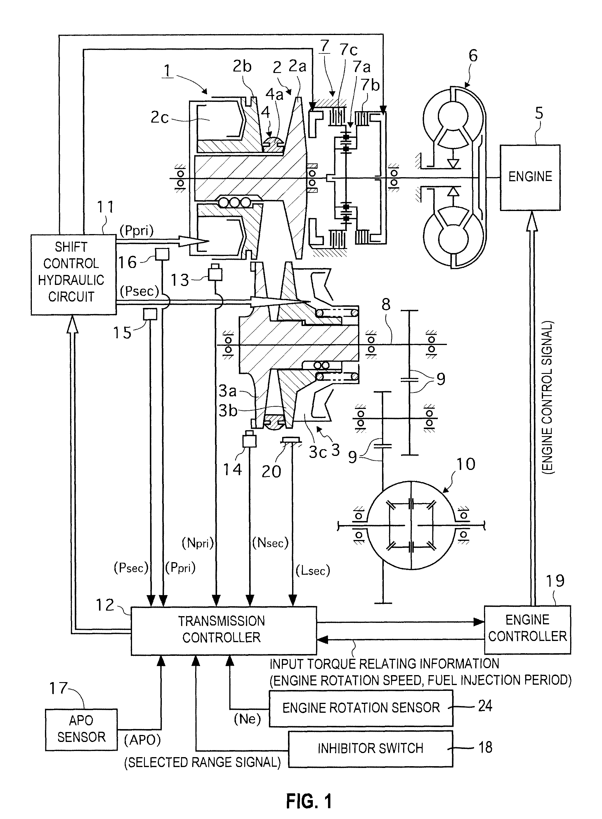
[0033]FIG. 1 schematically shows a power train of a vehicle equipped with a V-belt continuously variable transmission 1 provided with a control apparatus of a driving force in case of belt slipping according to the first embodiment of the present invention together with a control system thereof.

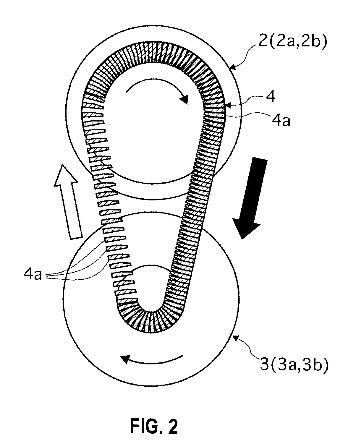
[0034]The V-belt continuously variable transmission 1 is provided with a primary pulley 2 and a secondary pulley 3 disposed such that pulley V grooves of both the pulleys are aligned within a plane perpendicular to axes of the pulleys and is configured by wrapping an endless V-belt 4 around the V grooves of the pulleys 2 and 3.

[0035]An engine 5 serving as a power source is disposed coaxially with the primary pulley 2 and a lockup torque converter 6 and a forward / reverse-switching mechanism 7 are interposed between the engine 5 and the primary pulley 2 from the side of the engine 5 in order....


PUM


Abstract

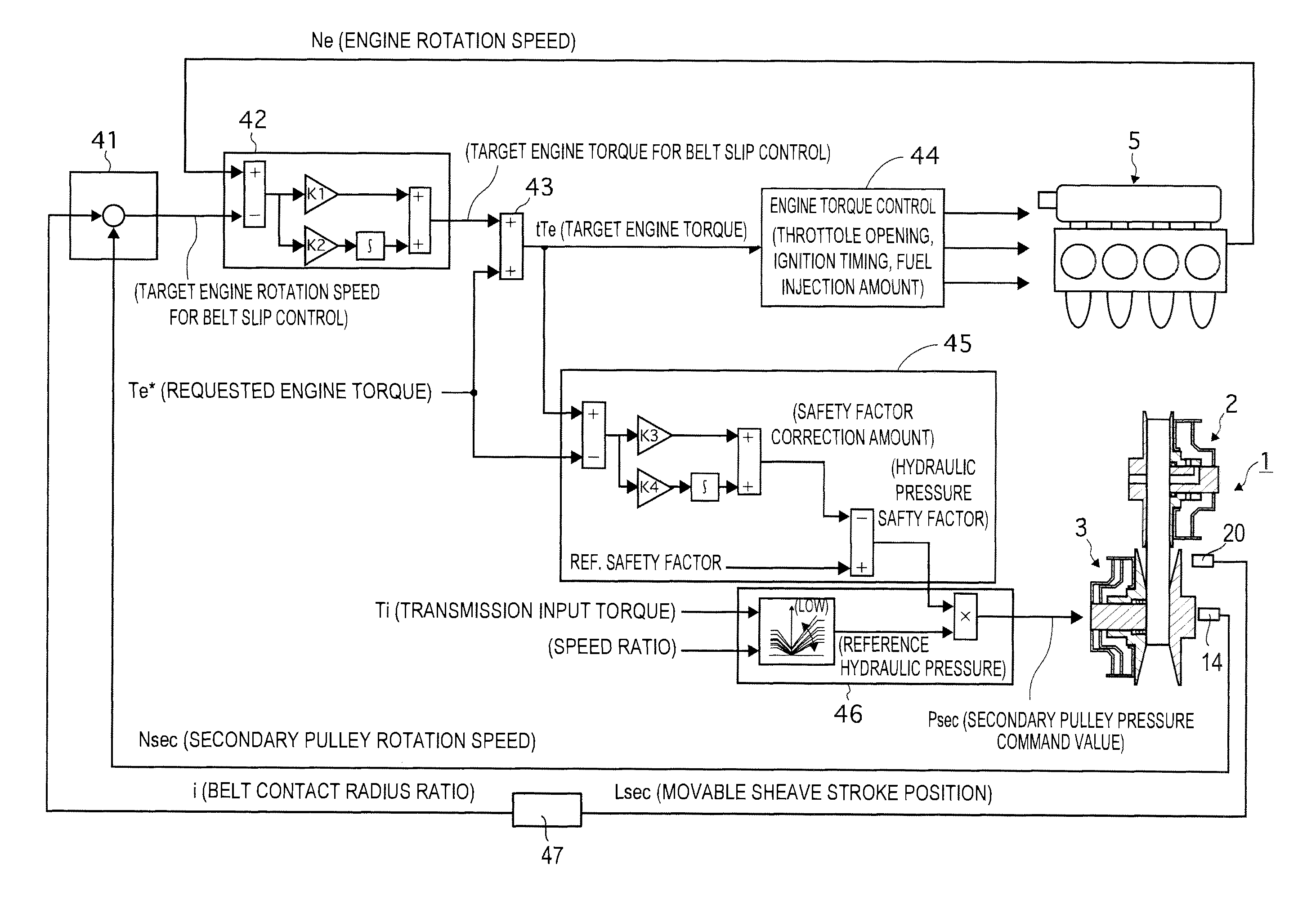
A control apparatus of a driving force in case of belt slipping includes a belt slip control detecting unit adapted to detect that the belt slip control is in execution, a belt contact radius ratio calculating unit adapted to calculate a belt contact radius ratio of the V-belt to the pulleys, and a power source output torque determining unit adapted to determine a target power output torque according to the belt contact radius ratio in execution of the belt slip control in response to signals from the belt slip control detecting unit and the belt contact radius ratio calculating unit.

Description

TECHNICAL FIELD OF THE INVENTION[0001]The present invention relates to a control apparatus of a driving force in case of belt slipping for a vehicle equipped with a V-belt continuously variable transmission.BACKGROUND OF THE INVENTION[0002]A V-belt continuously variable transmission is configured such that a V-belt is wrapped around a primary pulley on an input side and a secondary pulley on an output side so that transmission of rotation from a power source such as an engine and a motor can be performed.[0003]In order to make shift possible, such a configuration is adopted that the primary pulley and the secondary pulley are respectively configured such that each movable sheave which is one of sheaves forming pulley V-shaped grooves can be stroked in axial directions toward the corresponding other fixed sheave.[0004]In performing shift, stroke control is performed to the movable sheave of one pulley of these pulleys in an axial direction of coming close to or going away from a corr...

Claims


Application Information

Patent Timeline
Patent Type & Authority Patents(United States)
IPC IPC(8): G06F17/00F16H59/16F16H59/40F16H59/42F16H59/70F16H59/74F16H61/02F16H61/66F16H61/662F16H63/50
CPCB60W10/06B60W10/107B60W30/186F16H61/66272B60W2710/0666B60W2710/1022F16H2061/66277F16H2061/6629
Inventor YAMANAKA, TSUYOSHIYAMANAKA, MANABUSHIMANAKA, SHIGEKI
Owner NISSAN MOTOR CO LTD
Learn More