
Multiple anchor delivery tool

a multi-adjustment and tool technology, applied in the field of surgical tools, can solve the problems of reducing cardiac output, increasing total stroke volume, and ultimate weakening of the left ventricl

Active Publication Date: 2013-09-03
VALTECH CARDIO LTD
View PDF159 Cites 1296 Cited by
  • Summary
  • Abstract
  • Description
  • Claims
  • Application Information

AI Technical Summary

Benefits of technology

The patent describes a method for deploying anchors in cardiac tissue to treat certain conditions. The method involves using a rotating deployment element to screw the anchors into the tissue and a locking mechanism to secure the anchors in place. The method can also include the ability to withdraw and re-deploy the anchors. The technical effects of this patent include improved reliability and accuracy in heart valve repair and other medical procedures involving anchor deployment.

Problems solved by technology

Mitral regurgitation of blood from the left ventricle into the left atrium results in increased total stroke volume and decreased cardiac output, and ultimate weakening of the left ventricle secondary to a volume overload and a pressure overload of the left atrium.

Method used


Image

  • Multiple anchor delivery tool
  • Multiple anchor delivery tool
  • Multiple anchor delivery tool

Examples


Embodiment Construction

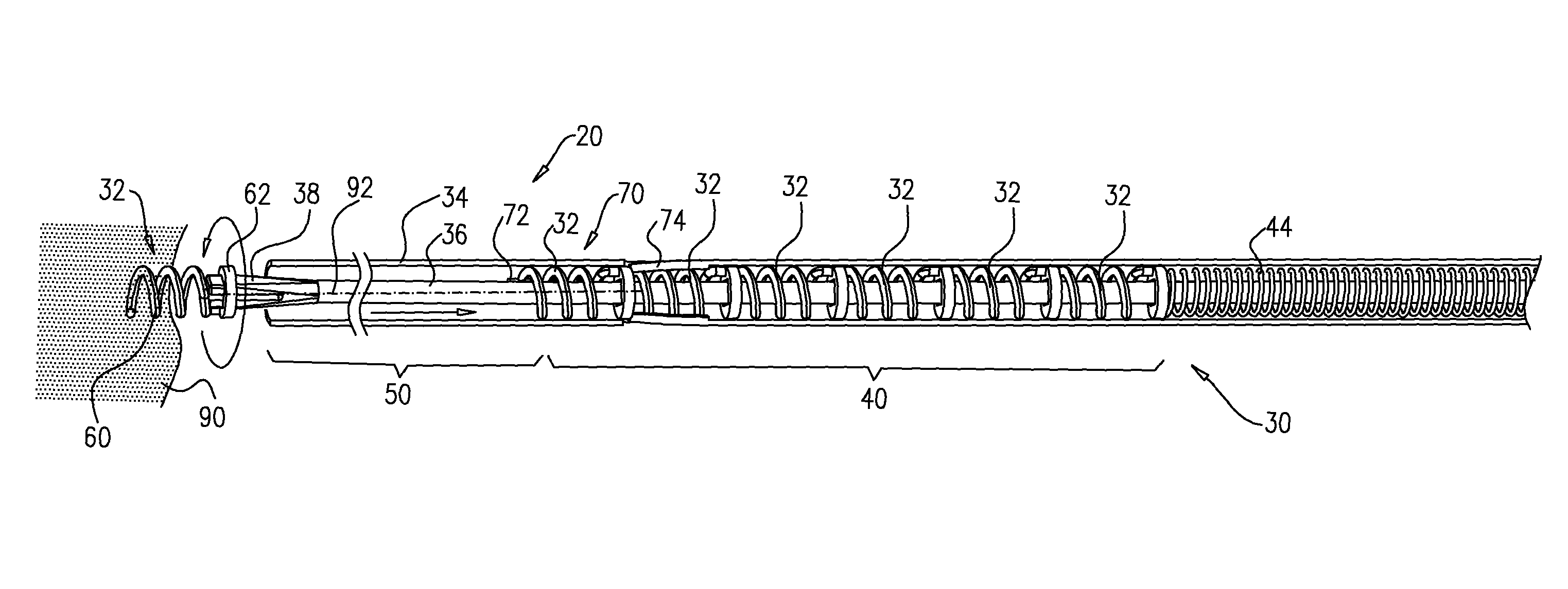
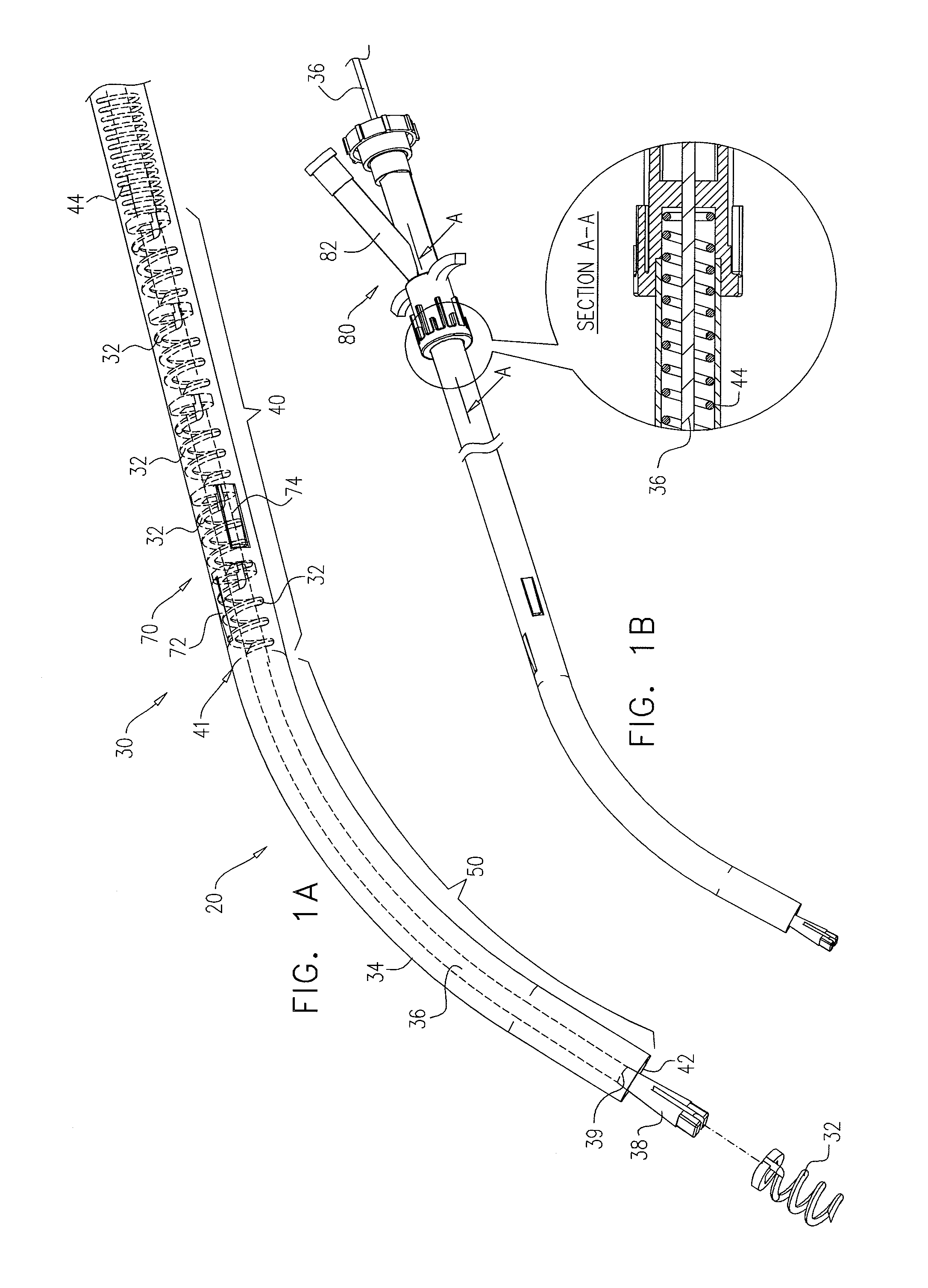
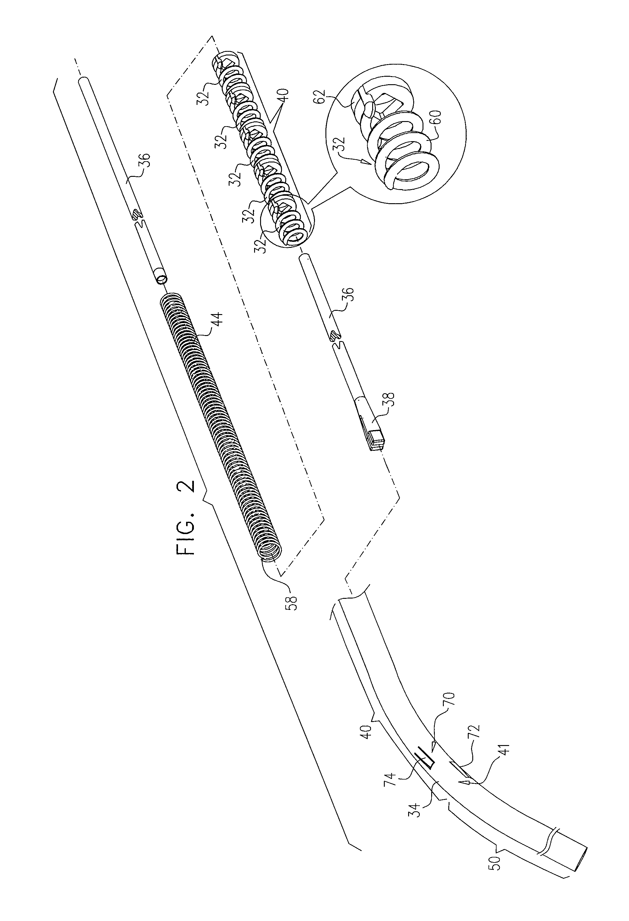
[0137]FIGS. 1A-B are schematic illustrations of an anchor deployment system 20, in accordance with an application of the present invention. Anchor deployment system 20 comprises an anchor deployment tool 30, which is configured to deliver a plurality of anchors 32 to respective sites within a body of a subject, and to couple the anchors to tissue at the sites. For some applications, tool 30 is configured to deploy anchors 32 to cardiac sites within the heart, such as in a vicinity of a valve annulus. Tool 30 comprises a flexible outer tube 34, within which is positioned a flexible inner shaft 36. Tool 30 further comprises a rotating deployment element 38, coupled to a distal shaft end 39 of inner shaft 36.

[0138]As shown in FIG. 1A, tool 30 (e.g., flexible outer tube 34) is configured to provide an anchor storage area 40, which is configured to initially store the plurality of anchors 32. The anchors are positioned within outer tube 34 such that inner shaft 36 passes through respecti...


PUM


Abstract

An anchor deployment tool includes a flexible outer tube, within which is positioned a flexible inner shaft, and a rotating deployment element coupled to a distal end of the shaft. The tool is configured to provide an anchor storage area, which initially stores a plurality of tissue anchors, such that the inner shaft passes through channels of the anchors along entire longitudinal lengths of the anchors, and the anchors are within the outer tube. The rotating deployment element is configured to directly engage the anchors in the anchor storage area one at a time, advance each of the anchors while engaged in a distal direction, and deploy each of the anchors through the distal tube end and into tissue of a subject. Other embodiments are also described.

Description

FIELD OF THE APPLICATION[0001]Some embodiments of the present invention relate in general to surgical tools, and more specifically to surgical tools for delivering tissue anchors.BACKGROUND OF THE APPLICATION[0002]Ischemic heart disease causes mitral regurgitation by the combination of ischemic dysfunction of the papillary muscles, and the dilatation of the left ventricle that is present in ischemic heart disease, with the subsequent displacement of the papillary muscles and the dilatation of the mitral valve annulus. Dilation of the annulus of the mitral valve prevents the valve leaflets from fully coapting when the valve is closed. Mitral regurgitation of blood from the left ventricle into the left atrium results in increased total stroke volume and decreased cardiac output, and ultimate weakening of the left ventricle secondary to a volume overload and a pressure overload of the left atrium.[0003]U.S. Pat. No. 6,296,656 to Bolduc et al. describes a helical fastener having a high ...

Claims


Application Information

Patent Timeline
Patent Type & Authority Patents(United States)
IPC IPC(8): A61B17/10
CPCA61B17/064A61B17/068A61F2/2445A61B2017/0649
Inventor CABIRI, OZGROSS, AMIRHAMMER, TALREICH, TALIFLAH, EHUD
Owner VALTECH CARDIO LTD
Learn More