
Device and method of automated construction of emergency flight path for aircraft

a flight path and aircraft technology, applied in the direction of process and machine control, instruments, etc., can solve the problems of inability to control the aircraft in question, increased collision risk, and inability to achieve the control of the aircraft, etc., to achieve great versatility

Inactive Publication Date: 2013-08-27
THALES SA
View PDF18 Cites 36 Cited by
  • Summary
  • Abstract
  • Description
  • Claims
  • Application Information

AI Technical Summary

Benefits of technology

The patent describes a device that can be used in different flight configurations and can be used with or without a pilot on board. It can also be used in a pilot assistance mode. Overall, it offers a lot of flexibility and can be adapted to different emergency situations.

Problems solved by technology

In particular, such cases include aircraft hijacking, medical emergencies, malfunctions affecting the aircraft's flight qualities (engine, pressurization, etc.), communication failures, making ground / air or air / air dialogue, and accordingly control of the aircraft in question impossible.
These failures increase the risk of collision and have a significant cost since they must be taken into account in air traffic control design to enable traffic reorganization when they occur.
In the extreme, these failures mean forcing the airplane to the ground by fighter planes.
They are therefore voluminous and complex.
Furthermore, they do not prescribe any single solution that can be directly integrated into a flight management system since a choice must be made from an infinite number of options.
This explains why in the present state of the art there is no solution for automatically or semi-automatically taking these procedures into account in a flight management system.
This is a significant drawback for aircraft with a pilot on board, since there is a heightened risk of misapplication of complex procedures by the crew and potential breaches of security are greater.
It is a completely unacceptable drawback for military aircraft whose pilot is not on board, known as drones.
But currently this cannot be ensured for a drone, particularly in the event of a communication failure.
In fact, if it is the control link that is interrupted, the extreme solution of instructions visually communicated by fighter planes is not applicable; if it is the link between the drone and its pilot that is interrupted, the latter cannot give any instruction to the aircraft.

Method used


Image

  • Device and method of automated construction of emergency flight path for aircraft
  • Device and method of automated construction of emergency flight path for aircraft
  • Device and method of automated construction of emergency flight path for aircraft

Examples


Embodiment Construction

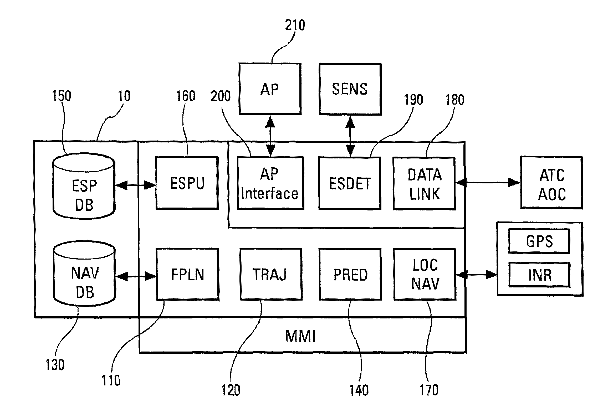
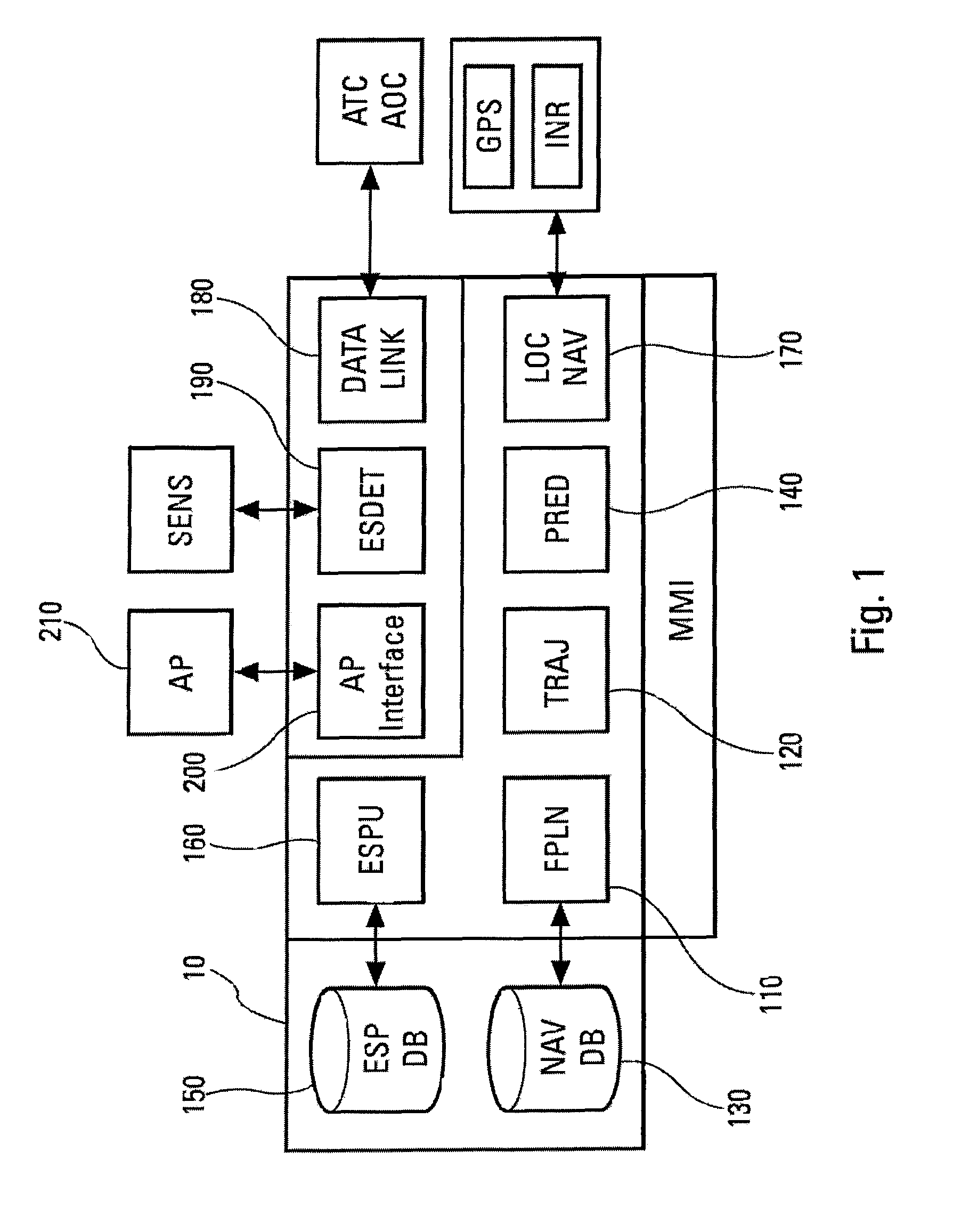
[0019]FIG. 1 shows the functional architecture of an FMS 10. Such systems are covered by the ARINC 702 standard (Advanced Flight Management Computer System, December 1996). They normally provide all or part of the functions of: navigation LOCNAV, 170, for optimum localization of the aircraft according to the means of geo-localization (GPS, GALILEO, VHF radio beacons, inertial units); flight plan FPLN, 110—Navigation database NAVDB, BDN, 130, for constructing geographical routes and procedures from data included in the databases (points, beacons, intercept or altitude legs, etc.); lateral flight path TRAJ, 120: for constructing a continuous flight path from flight plan points observing aircraft performances and confinement constraints (RNP); predictions PRED, 140: for constructing an optimized vertical profile on the lateral flight path; guidance, for guiding the aircraft on its 3 D flight path in the lateral and vertical planes, while optimizing speed; digital data link DATALINK, 18...


PUM


Abstract

The invention relates to a flight management system for manned or unmanned aircraft having to face an emergency situation such as hijacking of the aircraft, medical emergencies, situations of failures affecting the propulsion, pressurization or communication functions for example. It provides for a device and process for automatically or semi-automatically generating a flight plan compatible with international regulations and their national or local adaptations with possibilities of optimization according to navigation parameters.

Description

RELATED APPLICATION[0001]The present application is based on, and claims priority from France Application Number 05 12423, filed Dec. 7, 2005, the disclosure of which is hereby incorporated by reference herein in its entirety.BACKGROUND OF THE INVENTION[0002]The present invention applies to flight management systems for aircraft with or without a pilot on board. Such systems provide pilot assistance functions for determining the route to be followed by the aircraft to home in on its destination from its departure point taking into account the regulatory and operational constraints to be observed.[0003]These constraints include the procedures to be employed in given emergencies as prescribed by international organizations, state and airport authorities. In particular, such cases include aircraft hijacking, medical emergencies, malfunctions affecting the aircraft's flight qualities (engine, pressurization, etc.), communication failures, making ground / air or air / air dialogue, and accor...

Claims


Application Information

Patent Timeline
Patent Type & Authority Patents(United States)
IPC IPC(8): G01C23/00
CPCG08G5/0039G08G5/0056
Inventor COULMEAU, FRANCOIS
Owner THALES SA
Learn More