
Coherent receiver

Active Publication Date: 2013-08-20
NEC CORP
View PDF28 Cites 8 Cited by
  • Summary
  • Abstract
  • Description
  • Claims
  • Application Information

AI Technical Summary

Benefits of technology

[0020]In view of the above, an object of the present invention is to provide a coherent receiver capable of receiving a transmission signal transmitted as X polarization which is first transmission polarization or Y polarization which is second transmission polarization while recognizing it as X polarization or Y polarization reliably.
[0024]As the present invention is configured as described above, the present invention has an advantageous effect that a transmission signal, transmitted as X polarization which is first polarization or as Y polarization which is second polarization, can be received while being recognized as X polarization or Y polarization reliably.

Problems solved by technology

Accordingly, there is a problem that a transmission signal transmitted as X polarization or Y polarization is not received while being recognized as X polarization or Y polarization.

Method used


Image

  • Coherent receiver
  • Coherent receiver
  • Coherent receiver

Examples


first exemplary embodiment

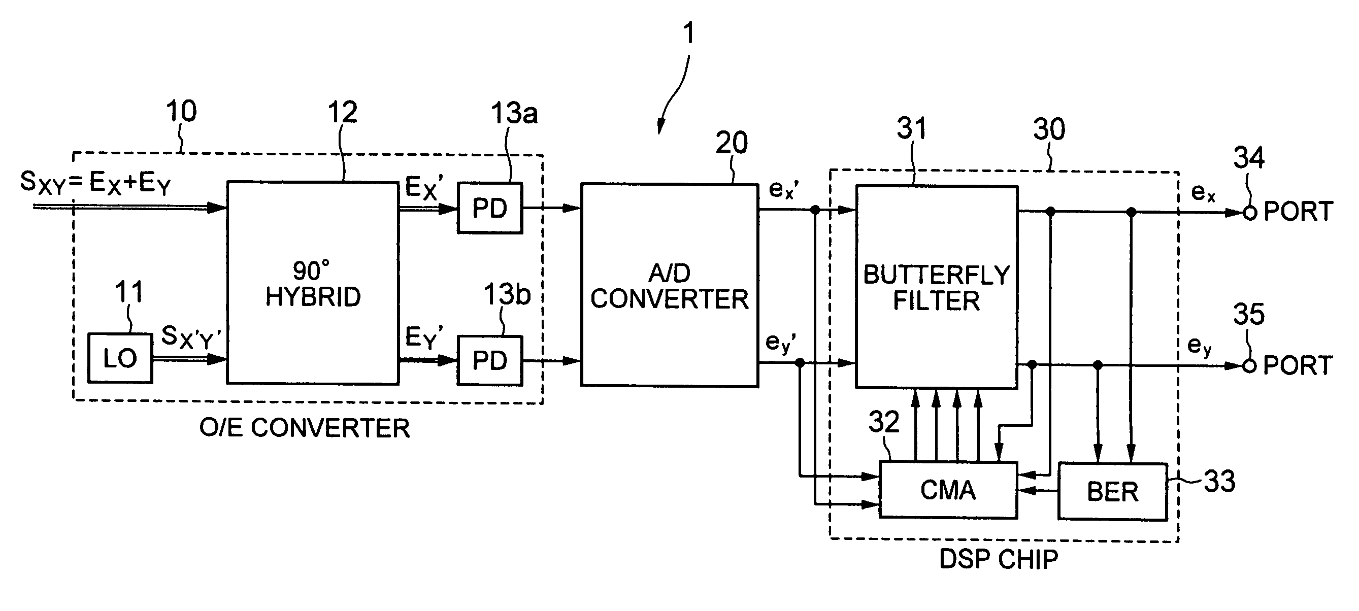
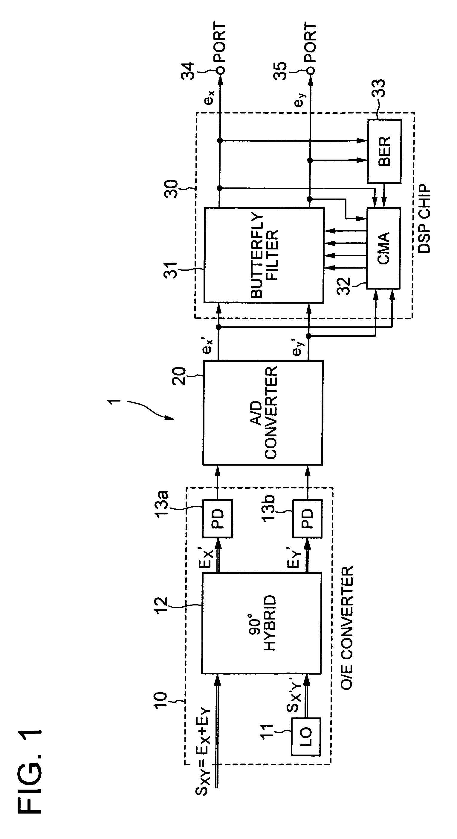
[0039]A first exemplary embodiment of the present invention will be described with reference to FIGS. 1 to 4. FIG. 1 is a block diagram showing the configuration of a coherent receiver. FIG. 2 is a block diagram showing the configuration of the digital signal processing (DSP) chip shown in FIG. 1. FIG. 3 is a block diagram for explaining an operation of the coefficient selection switch (SW) shown in FIG. 2. FIG. 4 is a sequence chart for explaining the initial setting of filter coefficients in the coherent receiver shown in FIG. 1.

[Configuration]

[0040]It should be noted that the present embodiment is a specific example of a coherent receiver explained in a fifth exemplary embodiment described below. Referring to FIG. 1, a coherent receiver 1 according to the present embodiment includes an optical to electrical (O / E) converter (detection means) 10, an analog to digital (A / D) converter (quantization means) 20, and a digital signal processing (DSP) chip (signal processing means) 30. Th...

second exemplary embodiment

[0073]Next, a second exemplary embodiment of the present invention will be described with reference to FIGS. 5 to 7. FIG. 5 is a block diagram showing another exemplary configuration of a digital signal processing (DSP) chip shown in FIG. 1. FIG. 6 is a block diagram for explaining an operation of the coefficient selection SW shown in FIG. 5. FIG. 7 is a sequence chart for explaining another example of initial setting of filter coefficients in the coherent receiver shown in FIG. 1.

[0074]The DSP chip 30 shown in FIG. 5 is used in the coherent receiver shown in FIG. 1. In FIG. 5, the same constitutional elements as those of the example shown in FIG. 2 are denoted by the same reference numerals. The example shown in FIG. 5 is different from the example of FIG. 2 in that the coefficient selection SW 32a is disposed between the CMA operation section 32a and the coefficient storing memory 32b. As such, in the example of FIG. 5, filter coefficients stored in the coefficient storing memory ...

third exemplary embodiment

[0088]Next, a third exemplary embodiment of the present invention will be described with reference to FIGS. 8 and 9. FIG. 8 is a block diagram showing the configuration of a coherent receiver according to the present embodiment. FIG. 9 is a block diagram showing the butterfly filter shown in FIG. 8 in detail. It should be noted that in FIG. 8, the same constituent elements as those shown in FIG. 1 are denoted by the same reference numerals.

[0089]Referring to FIG. 8, the coherent receiver 1 according to the third exemplary embodiment receives a QPSK-modulated quadrature signal as a quadrature signal. The coherent receiver 1 includes an optical to electrical (O / E) converter 10, an analog to digital (A / D) converter 20, and a digital signal processing (DSP) chip 30. In the present embodiment, the O / E converter also includes PDs 13c and 13d. Further, the CMA block 32 also includes carrier phase estimation (CPE) sections 36a and 36b.

[0090]As described relating to FIG. 1, the O / E converte...


PUM


Abstract

A coherent receiver 1 assigns a first transmission signal to first transmission polarization, assigns a second transmission signal to second transmission polarization, and receives a quadrature multiplexed signal formed by applying quadrature multiplexing to the first transmission polarization and the second transmission polarization. The coherent receiver includes a detection means 10 for detecting the first transmission polarization and the second transmission polarization according to prescribed first reception polarization and second reception polarization and obtaining a first detected signal and a second detected signal; a quantization means 20 for quantizing the first detected signal and the second detected signal and obtaining a first quantized signal and a second quantized signal; and a signal processing means 30 for, when filtering the first quantized signal and the second quantized signal using a prescribed filtering control algorithm to form a first demodulated signal and a second demodulated signal respectively, adjusting filter coefficients of the filtering control algorithm according to the first quantized signal and the second quantized signal and the first demodulated signal and the second demodulated signal, and outputting the first demodulated signal and the second demodulated signal to a first output terminal and a second output terminal, respectively.

Description

TECHNICAL FIELD[0001]The present invention relates to a coherent receiver, and in particular, to a coherent receiver which coherently detects polarization-multiplexed signals (quadrature multiplexed signals) and specifies transmission polarization.BACKGROUND ART[0002]In recent years, along with the spread of the Internet, the capacity of data traveling over networks (transmission capacity) has been increased. As such, in so-called large artery communication channels linking large cities, optical transmission channels in which the capacity per one channel is 10 gigabit per second (Gb / s) or 40 Gc / s have been introduced.[0003]In the optical transmission of 10 Gb / s, OOK (On-Off-Keying) is used as a modulation system. On the other hand, in the optical transmission of 40 Gb / s, as the optical pulse width is as short as 25 picosecond (ps), an influence of wavelength dispersion is large. As such, if OOK is used, optical transmission of 40 Gb / s is not suitable for long distance transmission. ...

Claims


Application Information

Patent Timeline
Patent Type & Authority Patents(United States)
IPC IPC(8): H04B10/60H04B10/61
CPCH04B10/60H04B10/611H04B10/6166H04L27/223H04B10/65
Inventor YASUDA, WAKAKOOGASAHARA, DAISAKUFUKUCHI, KIYOSHI
Owner NEC CORP
Learn More