Eureka AIR delivers breakthrough ideas for toughest innovation challenges, trusted by R&D personnel around the world.

Ergonomic portion measuring fluent material dispensing system

a dispenser and fluent material technology, applied in the direction of liquid/fluent solid measurement, container, volume measurement, etc., can solve the problems of user fatigue and accuracy reduction, waste of food, and inability to perform as well for the purpose at hand, so as to reduce user fatigue, improve productivity, and improve the effect of cleaning and storage options

Active Publication Date: 2013-08-20
FRANKE KINDRED CANADA LTD
View PDF21 Cites 14 Cited by
  • Summary
  • Abstract
  • Description
  • Claims
  • Application Information

AI Technical Summary

Benefits of technology

The present invention is a fluent material dispensing system that allows for easy and accurate dispensing of fluent materials in a foodservice environment. The system includes a bottle, plunger, and dispensing mechanism. The plunger slides inside the bottle and exerts a compressive force on the fluent material to force it out of the bottle. The dispensing mechanism is easy to operate with one hand and can adjust dispensing volumes. The system is designed ergonomically, complies with foodsafe standards, and can store and dispense a variety of fluent materials safely and efficiently. The system also includes a means to accurately dispense known fluent material volumes and for the user to easily adjust dispensing volumes.

Problems solved by technology

Prior art sauce dispensers are often based on known devices such as caulking guns or cake-icing dispensers to dispense fluent materials, but because they evolved from devices used for a different purpose, they often do not perform as well for the purpose at hand.
When dispensing with one hand, the user's wrist fatigues and accuracy is reduced.
Dispensers with gun-like or side projecting handle / triggers often obstruct a clear view of the dispensing target when used, thereby causing wasted food, lost efficiency and higher cost to the consumer.
For the same reason, dispensers with a handle / trigger that projects away from the sides of its fluent material container require a lot of room to store because their handle interferes with adjacent dispensers.
This can be problematic as sauces are often stored on a preparation rack and / or in a refrigerator.
This requires the purchase of redundant dispensing mechanisms and their storage with each dispenser, thus adding to cost, clutter, increased handling and washing, and the like.
A number of prior art designs of fluent material dispensers stand upright on their non-dispensing end leaving their dispensing end exposed to contamination, as well as causing their contents to flow to the non-dispensing end.
This deficiency requires that the user attempt to reverse the direction of the fluent material in order to dispense by shaking, jerking and hitting the dispenser.
This requirement is inefficient, unsafe and a poor design.
This creates the unnecessary requirement that the user fills the dispensing container extremely accurately or an air pocket will be formed between the piston and the foodstuff when the piston is pushed into the dispensing container.
The result is that sauce is spilled onto countertops or the floor, instead of dispensed onto the target food, and fouls the dispenser as well as creates a messy work environment.
Without a means to expel any air between the fluent material and the container's piston, foodstuffs will be wasted which will require more rigorous cleaning of dispensers and added expense.
Also, current designs have many extraneous and complex parts that are often hard to clean, which is an important factor when food safety and product maintenance is an issue.
Common prior art sauce dispensers have limited means to adjust accurate dispensing volumes, requiring much skill to dispense a known quantity and are often wasteful.
With less viscous materials however, the need to dispense accurately is necessary, but present devices do not have easy or efficient means to adjust the dispenser to produce different dispensing volumes as needed for different foodstuffs.
At best, a means to arrest the range of motion is available in some prior art, but the mechanism must be manually adjusted each time one wants to dispense different volumes, which often requires laborious disassembly of the dispenser or requires special tools.

Method used


Image

  • Ergonomic portion measuring fluent material dispensing system
  • Ergonomic portion measuring fluent material dispensing system
  • Ergonomic portion measuring fluent material dispensing system

Examples


Embodiment Construction

[0037]Invention elements will now be disclosed by reference to drawing figures. Elements will then be described in detail, and functional interactions between invention elements as well as groups of invention elements will then be described.

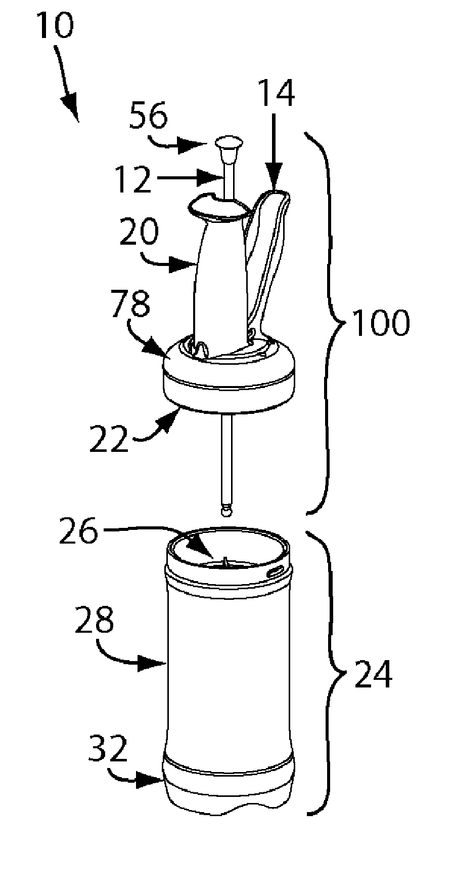
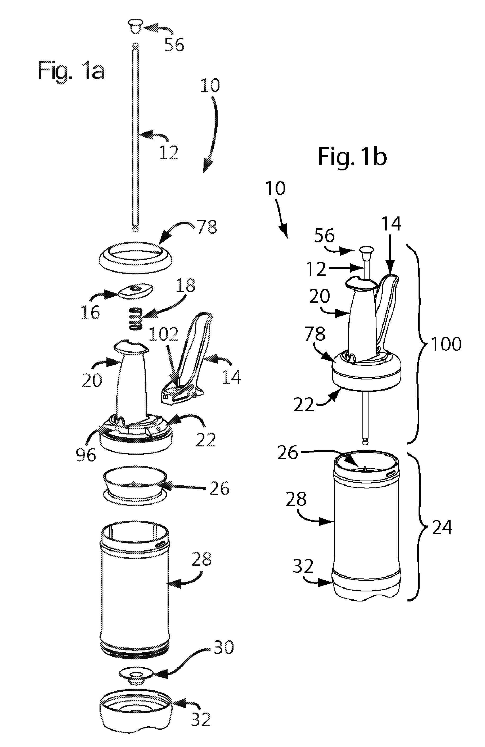
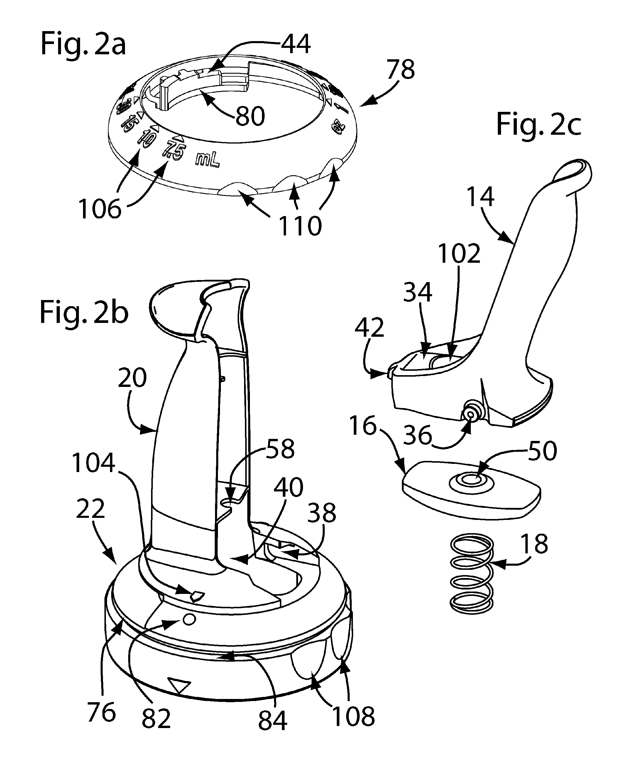
[0038]FIG. 1a, shows an isometric exploded view of the basic Dispenser 10 elements, namely a rod 12 with a rod cap 56, a plate 16, spring 18, handle 20, handle cap 22, plunger 26, bottle 28, outlet valve 30, and discharge cap 32. Also shown are a portion ring 78, a ledge 96, and a lever 14 with its rod port 102. (Note: a handle cap 22 is a cap that fits onto the top of a bottle 28 with a handle 20 as part of, and integrated with, its essential structure. While the handle 20 cannot be physically separated from the handle cap 22 in at least some embodiments, it can be logically identified as a sub element of its parent structure.) FIG. 1 b shows an isometric semi-exploded view of the dispenser 10 elements separated into two modular halves, namely t...


PUM


Abstract

A fluent material dispensing system comprising: a bottle, a plunger engaged inside the bottle, and a dispensing mechanism having a lever for operation of the plunger for fluid expulsion. The plunger may frictionally engage the bottle to a degree sufficient for holding the plunger in place against a force applied due to return motion of the lever. The dispensing mechanism may comprise a cap for attachment to an end of the bottle opposite a fluid outlet and a handle attached to the cap, the lever pivotally coupled to the cap, the lever and the handle aligned with the bottle. The dispensing mechanism may comprise a portioning mechanism configured to limit distance travelled by the lever from the rest position to the engaged position to a defined amount, thereby limiting expulsion of the fluid to a corresponding defined portion.

Description

FIELD OF INVENTION[0001]This invention relates in the general field of fluent material dispensers and more specifically to a dispensing system with ergonomic inline actuation integrated with portion measuring and modular attributes that contribute to food safety, ease of use and storage efficiency.BACKGROUND OF THE INVENTION[0002]Quick Service Restaurants often require a means to dispense various sauces & condiments (fluent materials) onto food in a controllable, foodsafe, and efficient manner. Fluent materials include foodstuffs ranging from oils and vinegars, viscous sauces like mayonnaise, and from smooth to chunky sauces containing particles such as chopped onion or chili seeds. Prior art sauce dispensers are often based on known devices such as caulking guns or cake-icing dispensers to dispense fluent materials, but because they evolved from devices used for a different purpose, they often do not perform as well for the purpose at hand.[0003]Fluent material dispensers styled af...

Claims


Application Information

Patent Timeline
Patent Type & Authority Patents(United States)
IPC IPC(8): B67D7/60B65D88/54
CPCB05C17/0126B05C17/00576
Inventor VAN WIJK, ADRIAN ALBERTRICHARDS, SAMUEL CHARLESMCDONALD, JAMES WILLIAM
Owner FRANKE KINDRED CANADA LTD
Why Eureka
Eureka Blog
Learn More