Method of manufacturing a switch system

a switch system and switch technology, applied in the field of filters, can solve the problem of driving up the cost of miniaturized filters

Active Publication Date: 2013-08-13
HARRIS CORP
View PDF17 Cites 2 Cited by
  • Summary
  • Abstract
  • Description
  • Claims
  • Application Information

AI Technical Summary

Problems solved by technology

These expensive development costs tend to drive up the cost of miniaturized filters.

Method used


Image

  • Method of manufacturing a switch system
  • Method of manufacturing a switch system
  • Method of manufacturing a switch system

Examples


Embodiment Construction

[0016]The invention is described with reference to the attached figures. The figures are not drawn to scale and they are provided merely to illustrate the instant invention. Several aspects of the invention are described below with reference to example applications for illustration. It should be understood that numerous specific details, relationships, and methods are set forth to provide a full understanding of the invention. One having ordinary skill in the relevant art, however, will readily recognize that the invention can be practiced without one or more of the specific details or with other methods. In other instances, well-known structures or operation are not shown in detail to avoid obscuring the invention. The invention is not limited by the illustrated ordering of acts or events, as some acts may occur in different orders and / or concurrently with other acts or events. Furthermore, not all illustrated acts or events are required to implement a methodology in accordance wit...


PUM

PropertyMeasurementUnit
pressureaaaaaaaaaa
temperatureaaaaaaaaaa
flexibleaaaaaaaaaa

Abstract

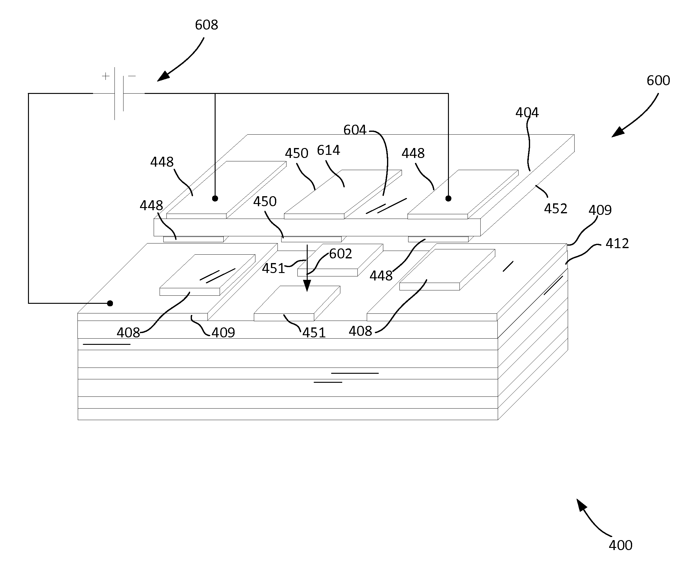
A method for manufacturing a micro electro-mechanical system (MEMS) switch system (600, 700) includes etching each of a plurality of base circuit layers (425) and a plurality of passive component substrate layers (412, 418, 42, 426). The method continues with laser milling of a first dielectric film (406) to create a spacer layer (405). A metal cladding (402, 403) formed on a flexible dielectric film layer 404 is etched so as to form a plurality of switch component features. Further laser milling is performed with respect to the flexible dielectric film layer to form at least one switch structure (448, 450). Thereafter, a stack (400) is assembled which is comprised of the spacer layer disposed between the flexible dielectric film layer and the plurality of base circuit layers. Additional layers can also be included in the stack. When the stack is completed, heat and pressure are applied to join the various layers forming the stack.

Description

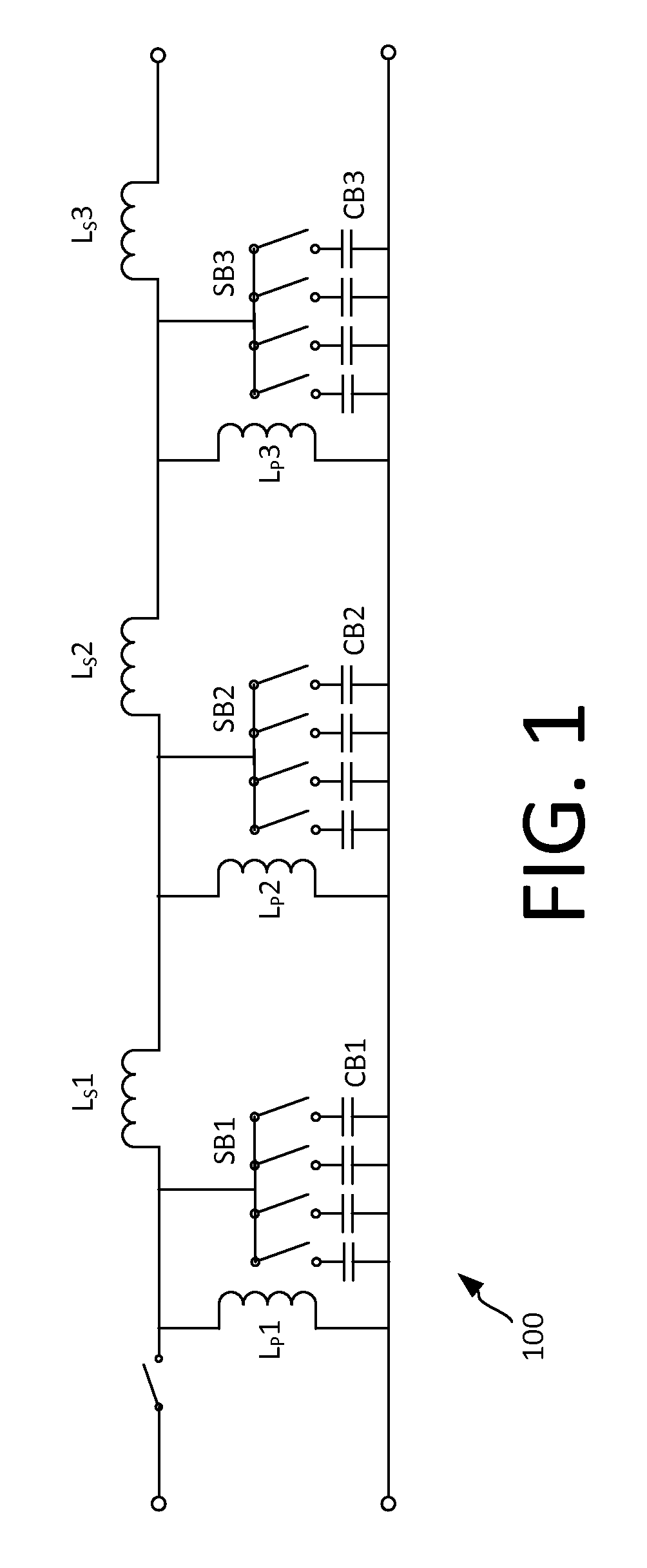
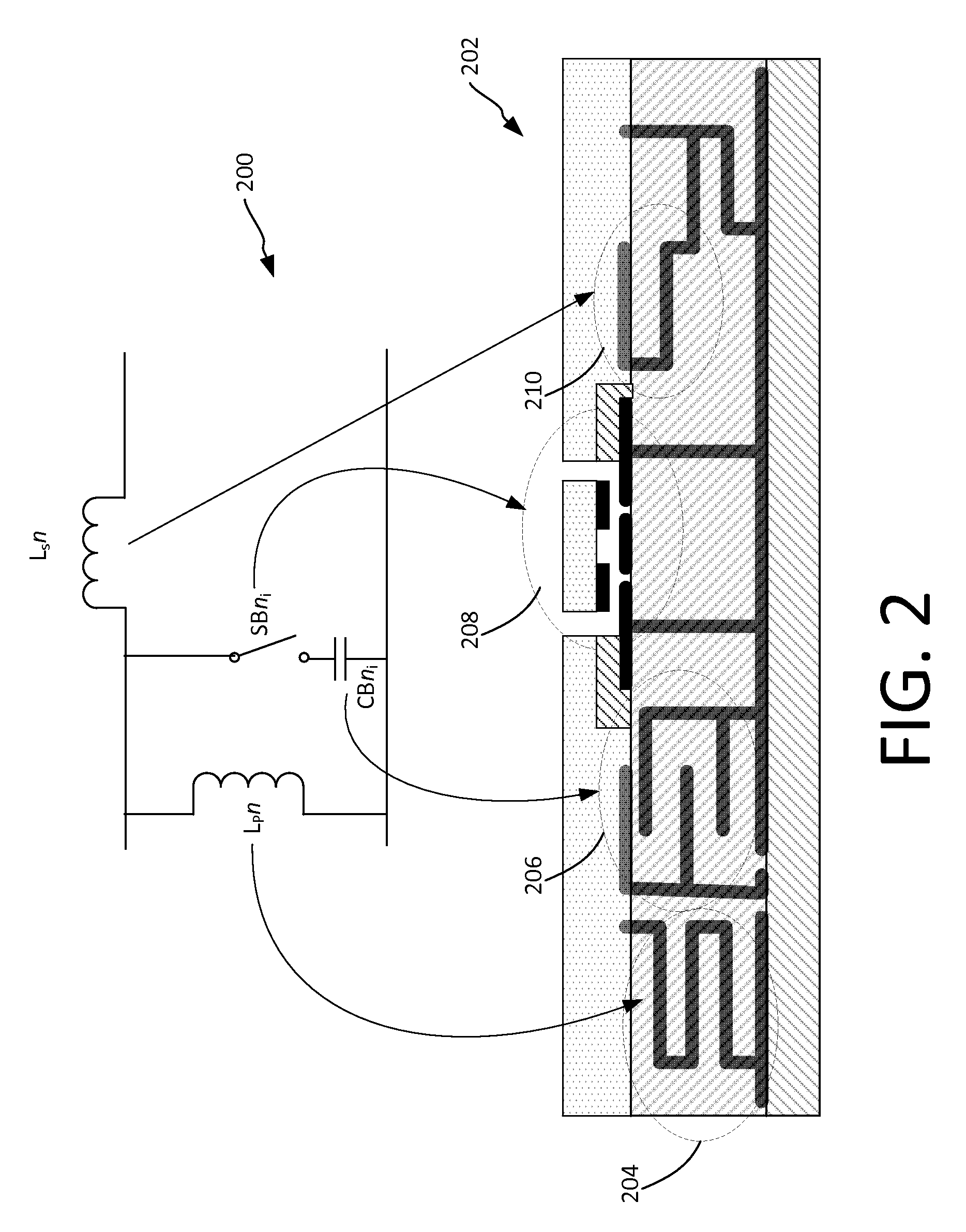
BACKGROUND OF THE INVENTION[0001]1. Statement of the Technical Field[0002]The inventive arrangements relate to filters, and more particularly to miniature filters that are low in cost and easily fabricated.[0003]2. Description of the Related Art[0004]Filter banks in radio frequency (RF) systems are typically comprised of thin-film passive devices and associated switching circuitry While these systems can work well, they generally require large investments in state-of-the-art processing technologies. These expensive development costs tend to drive up the cost of miniaturized filters.[0005]Micro electro-mechanical system (MEMS) type switch devices are known in the art. For example, meso-scale MEMS devices with a cantilevered beam have been constructed on a printed wiring board. In such systems, the cantilevered beam can be at least partially constructed of a polymer material to constitute its length. The beam is attached to a post on one end thereof and is cantilevered over the printe...

Claims


Application Information

Patent Timeline
Patent Type & Authority Patents(United States)
IPC IPC(8): C23F1/00
CPCB81C1/00341B81C1/00714H01H59/0009B81C2201/0143B81B2207/03H01H1/0036B81B2201/014B81B2203/0109B81B2207/99B81C2203/037H01H2001/0073
Inventor ROGERS, JOHN E.
Owner HARRIS CORP
Why Eureka
Try Eureka