Electrostatically atomizing device

a technology of atomizing device and atomizing chamber, which is applied in the direction of air humidification system, lighting and heating apparatus, heating types, etc., can solve the problems of inefficiency in discharging the mist generated in the atomizing barrel outward, and difficulty in efficiently discharging the mist out of the outlet port, so as to reduce the turbulent flow, efficiently discharging the mist out of the housing, and reducing the effect of turbulent flow

Inactive Publication Date: 2013-08-13
PANASONIC CORP
View PDF17 Cites 4 Cited by
  • Summary
  • Abstract
  • Description
  • Claims
  • Application Information

AI Technical Summary

Benefits of technology

[0007]With this arrangement, the air flows uniformly from the air pressure chamber into the atomizing barrel though the air inlets disposed in the peripheral wall of the atomizing barrel, which enables to discharge efficiently the mist generated within the atomizing barrel out of the outlet port. In short, the pressurized air introduced into the atomizing barrel can be well prevented from becoming turbulent within the atomizing barrel, and can avoid the adhesion of the mist on the interior wall of the atomizing barrel and accordingly the reduction in the amount of the mist to be discharged out through the outlet port, thereby making it possible to discharge the mist generated in the atomizing barrel outwardly in an efficient manner.
[0008]Preferably, the plural air inlets are disposed in a diametrically opposed relation with each other about an axis of the atomizing barrel so as to introduce the pressurized air effectively into the atomizing barrel through the uniformly spaced air inlets. Thus, it is possible to generate the forced air flow flowing from the emitter electrode at the center of the atomizing barrel and advancing outwardly through the outlet port without causing an eddy flow or turbulent flow, thereby discharging the mist efficiently outwardly of the housing.
[0009]The water feed means is preferably realized by a heat exchanger having a refrigerating part and a heat radiating part. In this instance, the refrigerating part is configured to cool the emitter electrode for allowing the water to condense on the emitter electrode. The housing is formed therein with an air flow path which is isolated from the air pressure chamber for cooling the heat radiating part, and also with a first air intake and a second air intake provided downstream of the fan respectively for flowing the pressurized air into the air pressure chamber and for flowing the pressurized air into the air flow path. Accordingly, the forced air flow produced by the fan is capable of discharging the mist out of the atomizing barrel and at the same time cooling the heat radiating part, thereby discharging the mist out of the housing efficiently.
[0010]In a preferred embodiment, the atomizing barrel is formed to have a rounded surface on its peripheral wall, and the air pressure chamber is formed at its one end with a first air intake. In this instance, the interior wall of the air pressure chamber is curved at a portion opposite of the first air intake from the atomizing barrel and is spaced substantially at a uniform distance from the exterior wall of the atomizing barrel. Thus, it is possible to restrain the turbulent flow at the portion of the air pressure chamber opposite of the first air intake, thereby introducing the pressurized air into the atomizing barrel efficiently so that the mist can be discharged outward effectively.
[0011]Furthermore, the air inlets are preferably disposed in the peripheral wall of the atomizing barrel at a portion not opposed to the first air intake. In this instance, the pressurized air flow flowing through the first air intake is allowed to advance directly into the atomizing barrel, thereby avoiding the turbulent flow within the atomizing barrel, and therefore enabling to efficiently discharge the mist outwardly of the atomizing barrel.

Problems solved by technology

However, in the conventional electrostatically atomizing device, although the air flow means forces the air to flow into the atomizing barrel, the air leaks outward throughout the pass which extends from the air flow means to the atomizing barrel to reduce the air of flowing thereinto.
Accordingly, it becomes difficult to discharge the mists out of an outlet port efficiently.
Furthermore, since it is difficult to uniformly introduce the air sent by the air flow means into the atomizing barrel, the air flow which is introduced from the air inlets into the atomizing barrel becomes turbulent so that the mists are not successfully discharged out of the outlet port, and the mists are attached to the inner wall of the atomizing barrel to reduce the mist of being discharged outwardly.
Consequently, it is not capable of discharging the mists generated within the atomizing barrel outward efficiently.

Method used


Image

  • Electrostatically atomizing device
  • Electrostatically atomizing device
  • Electrostatically atomizing device

Examples


Embodiment Construction

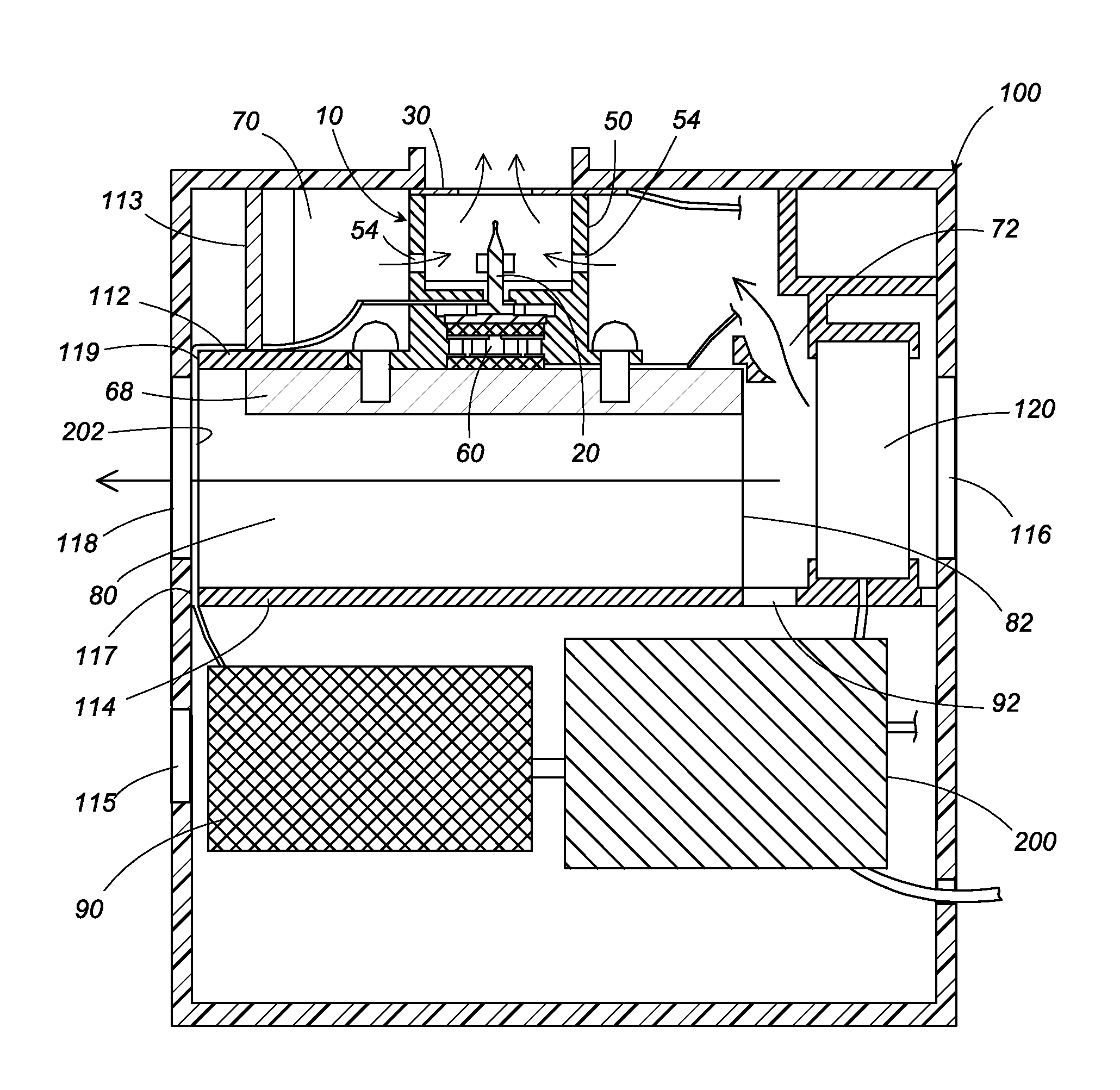
[0018]An electrostatically atomizing device in accordance with a first embodiment of the present invention is explained with reference to the attached drawings. As shown in FIG. 1, the electrostatically atomizing device includes an electrostatically atomizing unit 10 and a housing 100 which accommodates the unit. The housing 100 has, as shown in FIG. 4, a casing body 101 and a casing cap 102 which covers one side of the casing body 101.

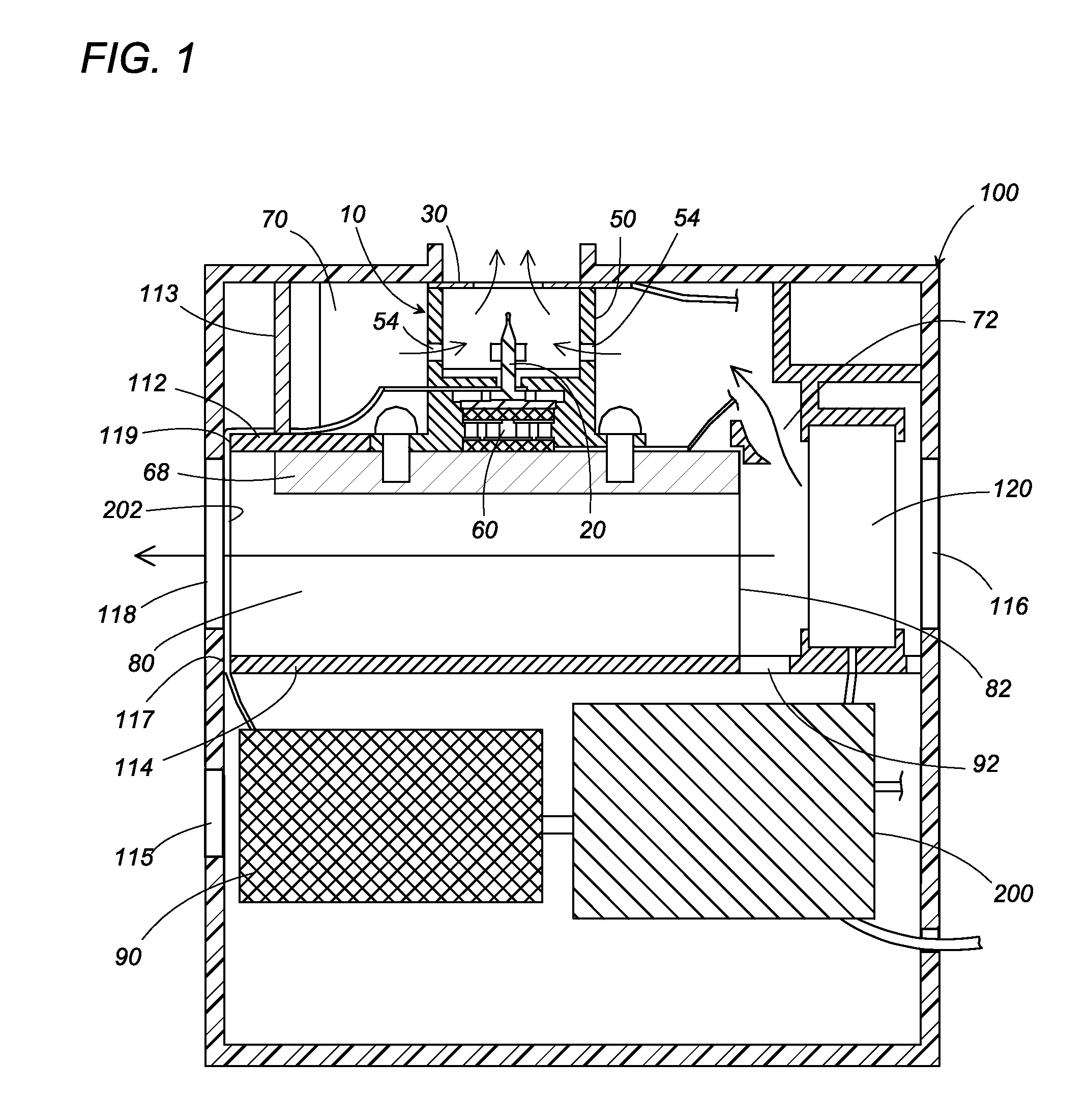
[0019]As best shown in FIG. 2, the electrostatically atomizing unit 10 includes an emitter electrode 20, an opposed electrode 30, and an atomizing barrel 50 which carries a heat exchanger 40. The emitter electrode 20 is disposed on a central axis of the atomizing barrel 50, and has its rear end fixed to a bottom face 51 of the atomizing barrel 50 so as to project its tip within the atomizing barrel 50. The opposed electrode 30 is configured into a ring shape having a circular window in its center, and is fixed to the front end of the atomizing barrel ...


PUM


Abstract

An electrostatically atomizing device has a housing and an electrostatically atomizing unit accommodated within the housing. The electrostatically atomizing unit includes an atomizing barrel and an emitter electrode disposed within the atomizing barrel and is configured to atomize water supplied to the emitter electrode at a tip of the emitter electrode and generate mist of charged minute water particles. Formed within the housing is an air pressure chamber which surrounds the atomizing barrel. The atomizing barrel is formed in its peripheral wall with a plurality of air inlets which are arranged circumferentially around the atomizing barrel to introduce pressurized air from the air pressure chamber for carrying the mist on the pressurized air introduced into the atomizing barrel from the plural air inlets and discharging the mist outwardly of the housing.

Description

TECHNICAL FIELD[0001]The present invention relates to an electrostatically atomizing device which electrostatically atomizes water so as to generate a mist of charged minute particles of nanometer sizes.BACKGROUND ART[0002]Conventionally, as disclosed in the International Patent Publication No. WO 2005 / 097339, an electrostatically atomizing device is known to electrostatically atomize water for generating a mist of charged minute particles of a nanometer size. The electrostatically atomizing device has an emitter electrode, a water feed means which is configured to give water on the emitter electrode, an atomizing barrel which defines an atomizing space in its interior and holds the emitter electrode in the space, and a high voltage applying section which applies a high voltage to the emitter electrode. With the high voltage applied to the emitter electrode, the water supplied on the emitter electrode is electrostatically atomized for generating the mist of charged minute particles ...

Claims


Application Information

Patent Timeline
Patent Type & Authority Patents(United States)
IPC IPC(8): B05B5/00
CPCB05B5/001B05B5/03F24F6/14B05B5/0533F24F2006/143Y02B30/545Y02B30/54
Inventor YANO, TAKESHIHIRAI, TOSHIHISAWADA, SUMIOSUGAWA, AKIHIDEMATSUMOTO, TATSUHIKOAKISADA, SHOUSUKE
Owner PANASONIC CORP
Why Eureka
Try Eureka