Granular spreader and method

a granular spreader and surface technology, applied in the direction of centrifugal wheel fertilisers, ways, instruments, etc., can solve the problems of insufficient and uneven dispersion of granules, and achieve the effect of preventing “flying” and adding stability

Inactive Publication Date: 2013-07-23
MAGNUS LOREN C
View PDF9 Cites 9 Cited by
  • Summary
  • Abstract
  • Description
  • Claims
  • Application Information

AI Technical Summary

Benefits of technology

[0015]The hopper also includes a series of internal dividers to section and allow for even separation of contained granules. The dividers extend from the top of the hopper to approximately a few inches above the egress and dispersion tubes and assist in maintaining the granules in the hopper somewhat level, while the granular spreader is in use on a sloped surface such as a race track. Due to the unevenness or tilt of a race track, with one side of the track being of higher elevation, should the dividers not be used, the granules tend to slide to the lower side, causing insufficient and unevenness of granule dispersion.
[0016]A pair of flexible flaps are affixed to the bottom of the hopper to assist in controlled distribution of the exiting granules and to prevent “fly”. The flaps consist of a first short or bottom flap which is affixed proximate the front hopper panel at the egress tube while a second longer or top flap is affixed proximate the rear hopper panel in opposing relation to the bottom flap. The bottom flap is folded back at its terminal end towards the front hopper panel onto itself and attached thereto such as by bolts or the like and includes a metal strip therein for stability which extends almost the full length of the bottom flap. A plurality of strip baffles are mounted at approximately forty-five degrees to the hopper travel direction on the top surface of the bottom flap, below the top flap to provide guidance in the direction of release to the exiting granules for contacting spilled liquids on the track surface. The baffles are affixed through the bottom flap and to the metal strip for added stability. The baffles while assisting in flow direction also insure a space is maintained between the top and bottom flaps for proper granular distribution.
[0017]To further assist in granule distribution and to insure the granules absorb spilled liquids, a rotatable scrubber having bristles is affixed rearwardly of the hopper which can be raised and lowered by an electric winch driven by power from the vehicle. The winch is maintained within a closed compartment inside the hopper proximate the top and the winch cable with a hook exits an aperture in the rear panel of the hopper to attach to a D-ring on the top of the scrubber. The winch is remotely operated by the vehicle driver using a wired remote control whereby the scrubber can be lowered so the bristles contact the race track surface to urge the deposited granules into spilled liquids. An adjustable target is moveably affixed to the driver's side of the scrubber so the driver of the vehicle can, for example look in the side mirror and see the target position (up or down) of the scrubber. A pair of chains extend from side rods of the scrubber frame through holes in the top flap and are affixed to the metal strip on the short bottom flap to assist in maintaining the usual position of the flaps and to prevent the flaps from becoming displaced, should the vehicle need to backup during granular spreading. A pair of turnbuckles are attached at one end to the scrubber frame side rods and at the other end to the scrubber to allow for adjusting to change the angular position of the scrubber, such as lengthening or shortening to thereby angle the position of the scrubber relative to the track surface to insure all bristles are flat against the track.

Problems solved by technology

Due to the unevenness or tilt of a race track, with one side of the track being of higher elevation, should the dividers not be used, the granules tend to slide to the lower side, causing insufficient and unevenness of granule dispersion.

Method used


Image

  • Granular spreader and method
  • Granular spreader and method
  • Granular spreader and method

Examples


Embodiment Construction

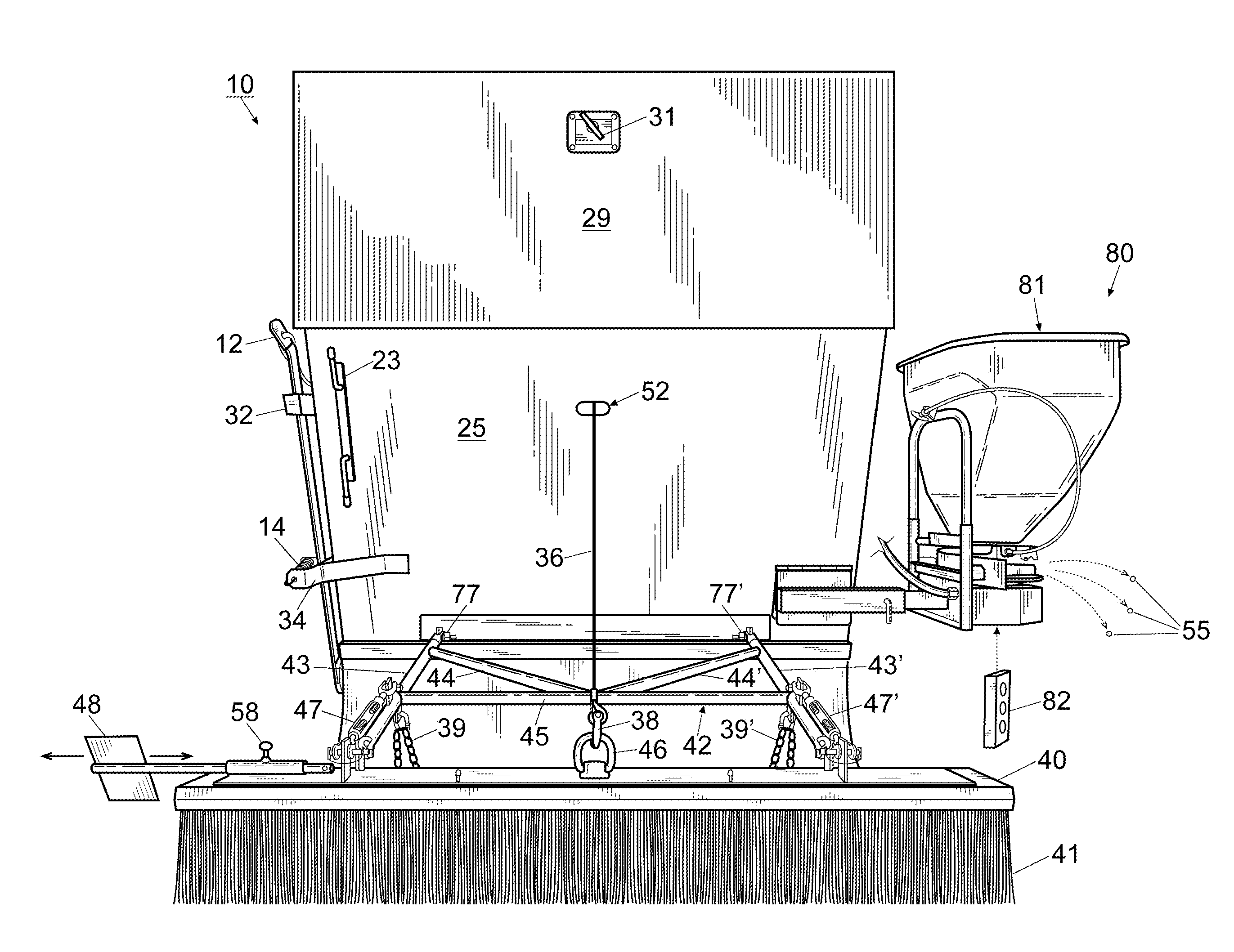
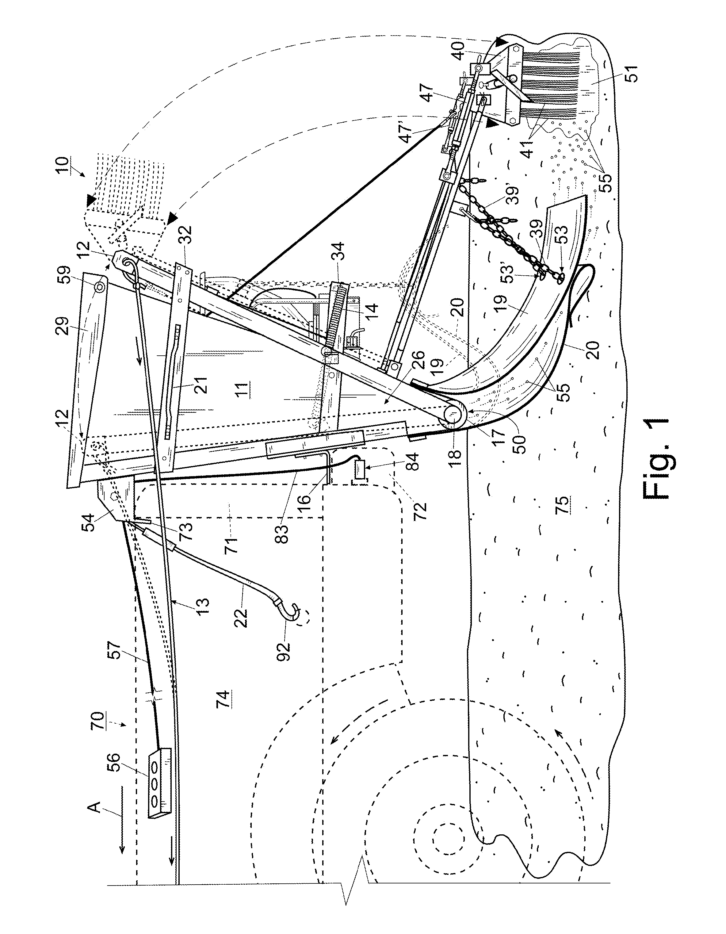
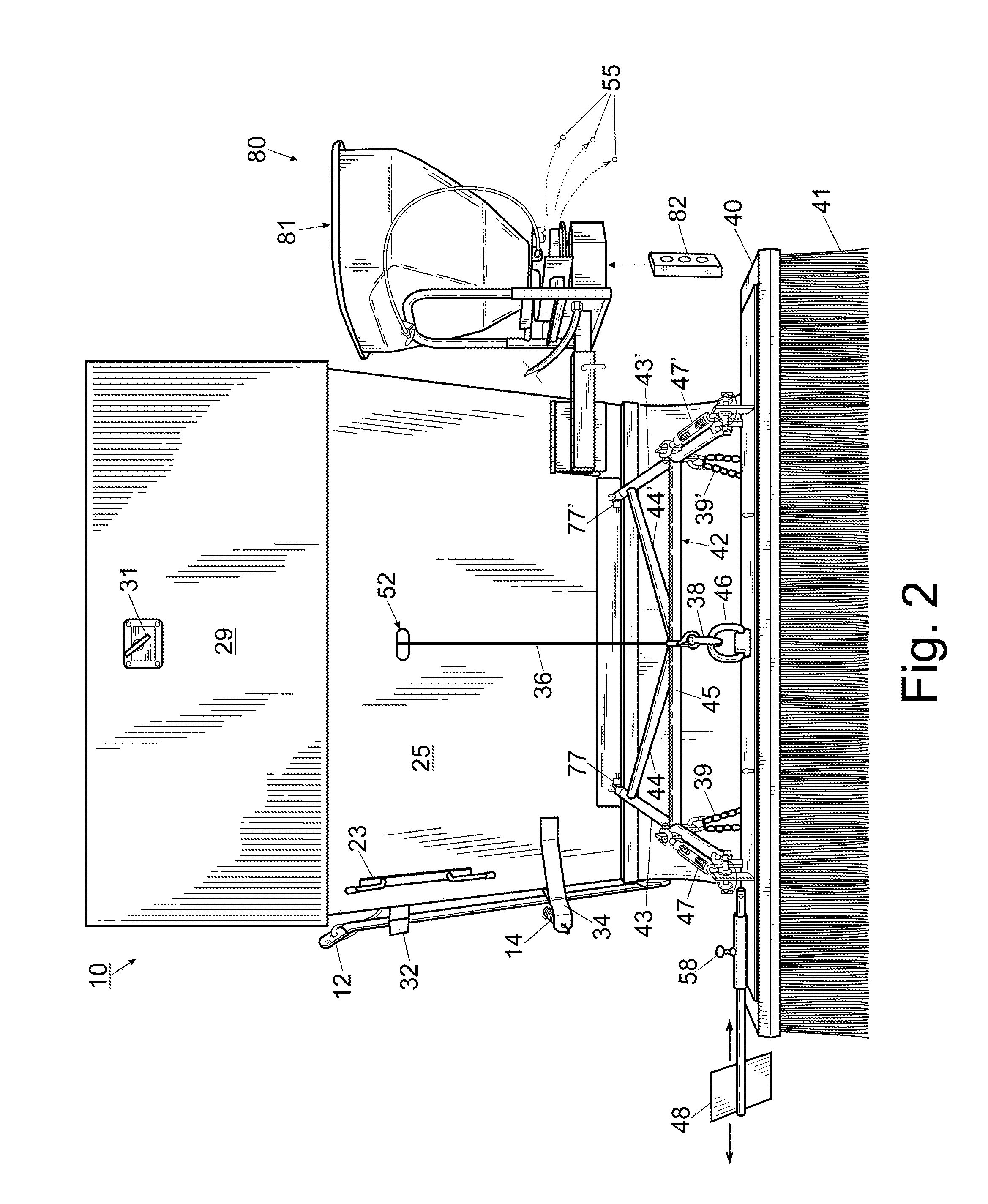
[0025]For a better understanding of the invention and its operation, turning now to the drawings, FIG. 1 shows preferred granular spreader 10 affixed to tailgate 71 of conventional pickup truck 70 in schematic representation. Granular spreader 10 is used for surface spreading various types of small, fine particles such as oil absorbents, salt, fertilizers, ground clay and for other materials and purposes as needed. Preferred granular spreader 10 includes V-shaped hopper 11 formed preferably from 0.090 inches (2.28 mm) T-6061 aluminum sheets composed of front panel 24, rear panel 25 and V-shaped side panels 26, 26′ as shown in FIGS. 1-4. Lid 29 is also formed from 0.090 inches (2.28 mm) T-6061 aluminum sheets and pivotally affixed to hopper 11 with pins 59 (FIG. 1), 59′ (FIG. 3). Hopper 11 has a capacity of 500-800 pounds of granular materials such as a conventional oil absorbent however other granular materials may weigh more or less, depending on the particular material selected.

[0...


PUM


Abstract

A granular spreader having a V-shaped hopper for distribution of oil absorbing granules can be used on race track spills. The granular spreader is towed by a vehicle such as a pickup truck during racing intervals. A rotatable scrubber is affixed to the hopper which can be lowered by an electric winch to contact the race track to urge the deposited granules into the spilled liquid. A pair of flexible flaps are affixed to the bottom of the hopper to assist in distribution and to prevent the fine granule particles from being blown away before contacting the spilled liquids. A cart is also provided for storing the granular spreader during periods of non-use.

Description

FIELD OF THE INVENTION[0001]The invention herein pertains to granular distribution onto a surface and particularly pertains to a granular spreader which can be affixed to and towed by a vehicle for the distribution of oil absorbing granules onto a race track to absorb liquid waste and spills.DESCRIPTION OF THE PRIOR ART AND OBJECTIVES OF THE INVENTION[0002]Hoppers and distributors for granular materials such as seed, grain, salt, fine clay, oil absorbents, fertilizers and the like have long been used. Small granular distributors are usually hand operated whereas larger spreaders are often manually rolled along the ground or other surface. Bigger spreaders are generally towed by a motorized vehicle such as a tractor or truck. Spreaders can be used on lawns, streets, golf courses, race tracks and the like. Most municipalities employ different types of spreaders to distribute salt on streets and highways during cold, inclement weather.[0003]Golf courses often use spreaders to distribut...

Claims


Application Information

Patent Timeline
Patent Type & Authority Patents(United States)
IPC IPC(8): A01C3/06A01C7/00A01C15/00E01C19/20
CPCE01C19/2005E01H1/001A01C15/10E01C19/203
Inventor MAGNUS, LOREN C.
Owner MAGNUS LOREN C
Why Eureka
Try Eureka