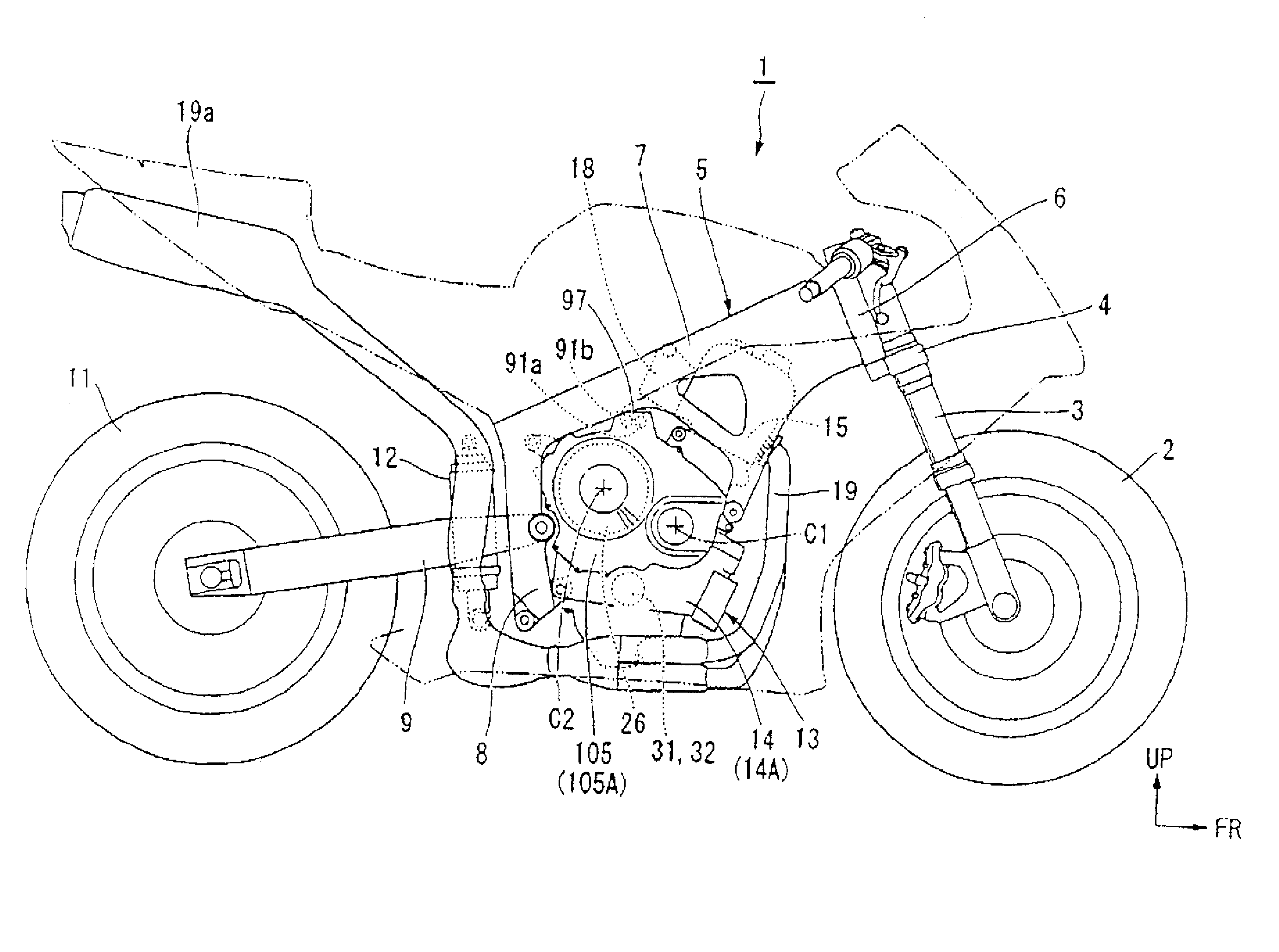
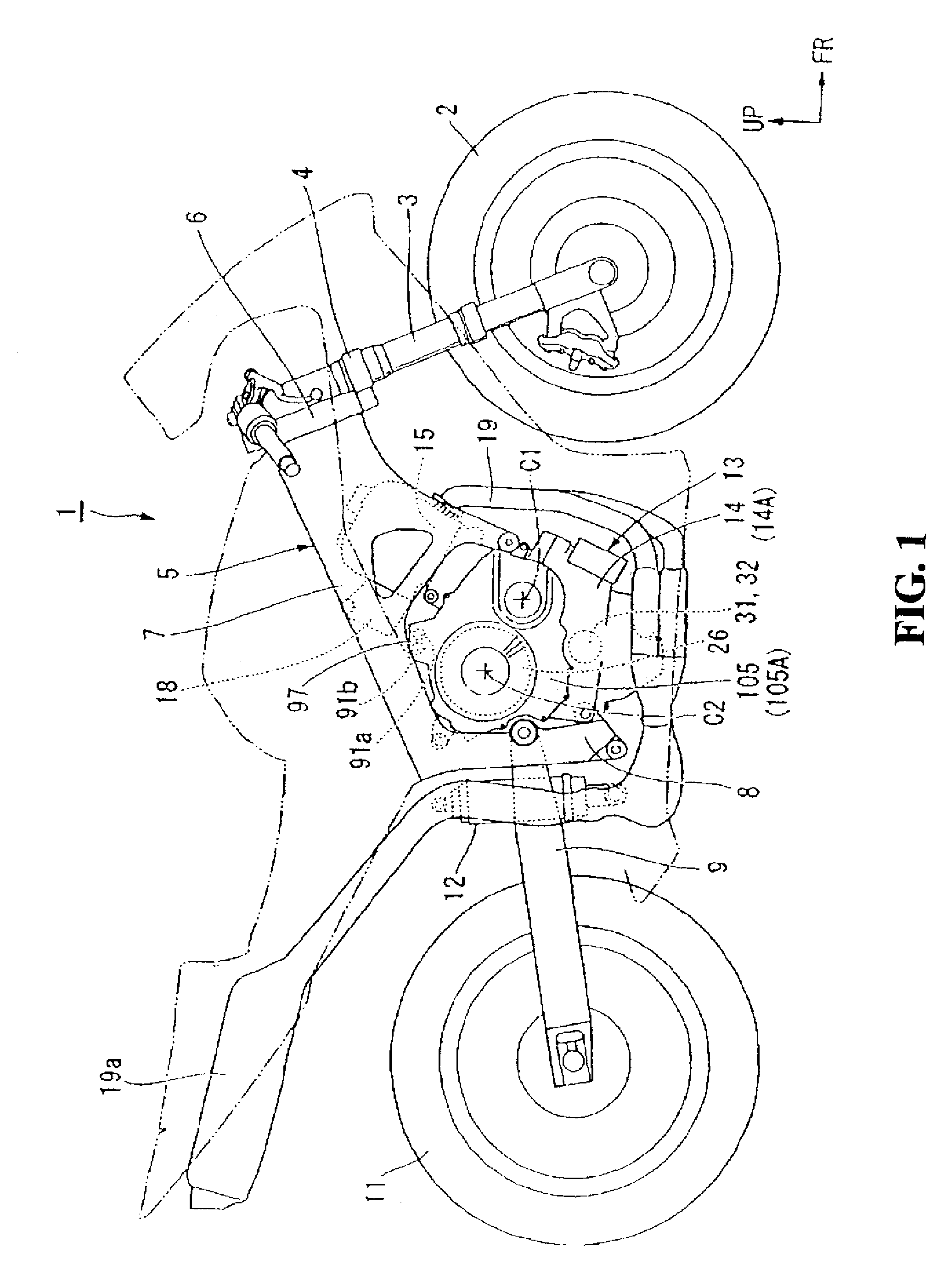
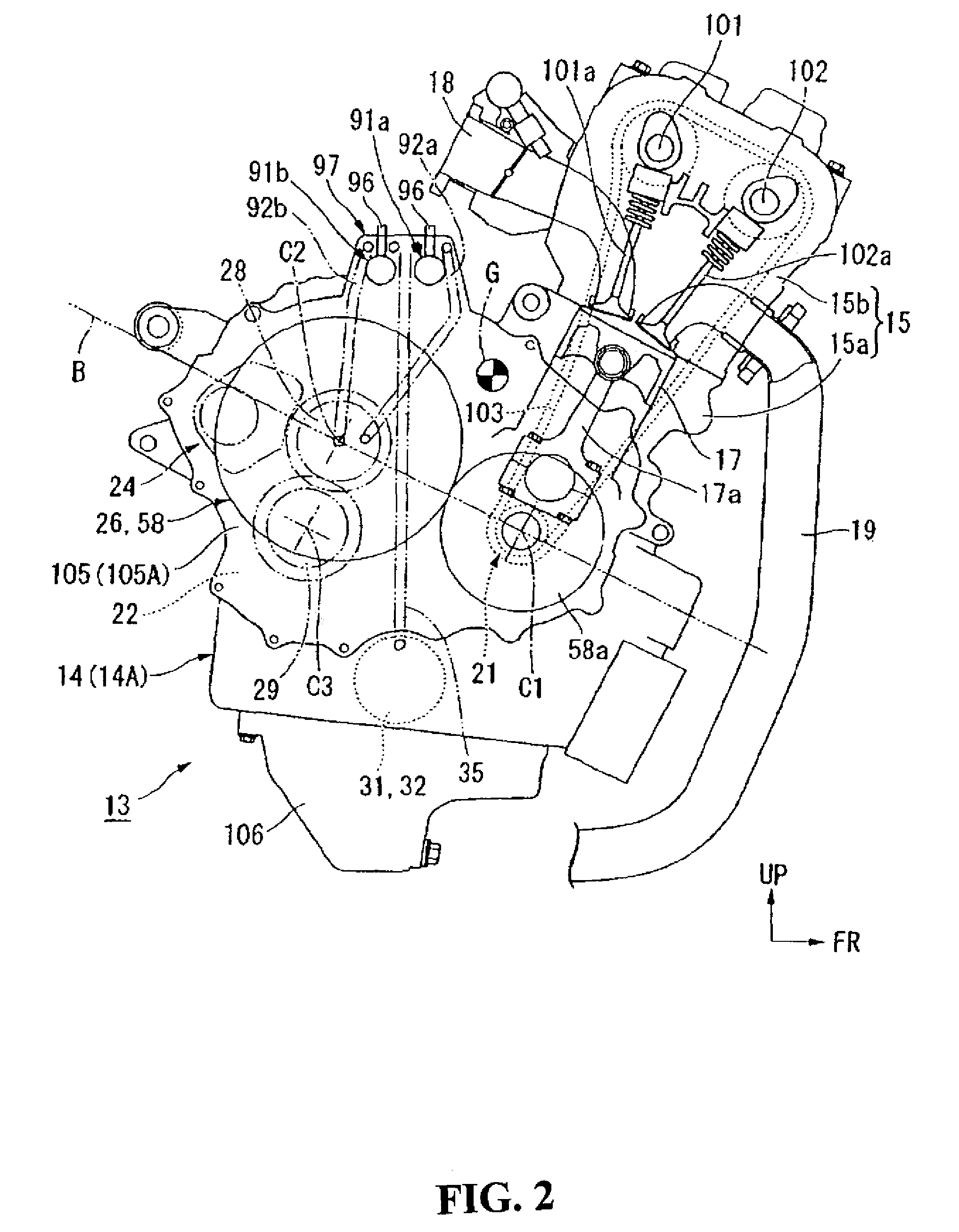
Engine including clutch actuator
a clutch actuator and clutch technology, applied in the direction of crankshaft transmission, clutch roller based transmission, cycles, etc., can solve the problems of increasing both weight and cos
- Summary
- Abstract
- Description
- Claims
- Application Information
AI Technical Summary
Benefits of technology
Problems solved by technology
Method used
Image
Examples
second embodiment
[0111]Next, the present invention will be described with reference to FIGS. 9 and 10.
[0112]Where an engine 13a of the second embodiment mainly differs from the engine 13 of the first embodiment is that the clutch actuators 91a and 91 are arranged below the twin clutch 26, and the same reference numerals are given to parts identical to those in the first embodiment. Thus, the explanation thereof will be omitted.
[0113]The respective clutch actuators 91a and 91b are arranged inside an actuator installing part 97a located at a lower portion (below the twin clutch 26) of the clutch case 105A in a state where the axis lines thereof are directed in the left-right direction and they are arranged in parallel with each other and in a vertically aligned manner.
[0114]The actuator installing part 97a protrudes, for example, upward (inside the clutch case 105A) at a lower portion of the clutch case 105A and in the vicinity of the second oil pump 32, and is divided, in the left-right direction, in...
third embodiment
[0120]Next, the present invention will be described with reference to FIGS. 11 and 12.
[0121]Where an engine 13b of the third embodiment mainly differs from the engine 13 of the first embodiment is that the clutch actuators 91a and 91 are arranged behind the twin clutch 26, and the same reference numerals are given to parts identical to those in the first embodiment. Thus, the explanation thereof will be omitted.
[0122]The respective clutch actuators 91a and 91b are arranged inside an actuator installing part 97b located at a rear portion (behind the twin clutch 26) of the clutch case 105A and below the dividing plane B in a state where the axis lines thereof are directed in the left-right direction and they are arranged in parallel with each other and placed above and below.
[0123]The actuator installing part 97b protrudes, for example, forward (inside the clutch case 105A) at a rear portion of the clutch case 105A, and is divided, in the left-right direction, into the crankcase 14-si...
fourth embodiment
[0134]Next, the present invention will be described with reference to FIG. 15.
[0135]Where an engine 13c of the fourth embodiment mainly differs from the engine 13 of the first embodiment is that the clutch actuators 91a and 91 are arranged in front of the twin clutch 26, and the same reference numerals are given to parts identical to those in the first embodiment. Thus, the explanation thereof will be omitted.
[0136]The respective clutch actuators 91a and 91b are arranged inside an actuator installing part 97c located at a front portion of the clutch case 105A in a state where the axis lines thereof are directed in the left-right direction and they are arranged in parallel with each other and placed above and below.
[0137]The clutch actuators 91a and 91b are arranged behind a chain line on the rear side of the cam chain 103 and arranged adjacent to the center of gravity C of the engine located substantially right above the crankshaft 21. The left and right directions of the clutch act...
PUM
 Abstract
Description
Claims
Application Information
 - R&D
- Intellectual Property
- Life Sciences
- Materials
- Tech Scout
- Unparalleled Data Quality
- Higher Quality Content
- 60% Fewer Hallucinations
Browse by: Latest US Patents, China's latest patents, Technical Efficacy Thesaurus, Application Domain, Technology Topic, Popular Technical Reports.
© 2025 PatSnap. All rights reserved.Legal|Privacy policy|Modern Slavery Act Transparency Statement|Sitemap|About US| Contact US: help@patsnap.com


