
Torque rotor and method for manufacturing the same

a technology of torque rotor and torque rotor, which is applied in the field of torque rotor, can solve the problems of magnetic field declination, error of torque measurement value, magnet breakage, etc., and achieve the effect of preventing inflow, preventing idle rotation of the yoke, and preventing the degradation of the roundness of the magn

Active Publication Date: 2013-07-09
HL MANDO CORP
View PDF5 Cites 7 Cited by
  • Summary
  • Abstract
  • Description
  • Claims
  • Application Information

AI Technical Summary

Benefits of technology

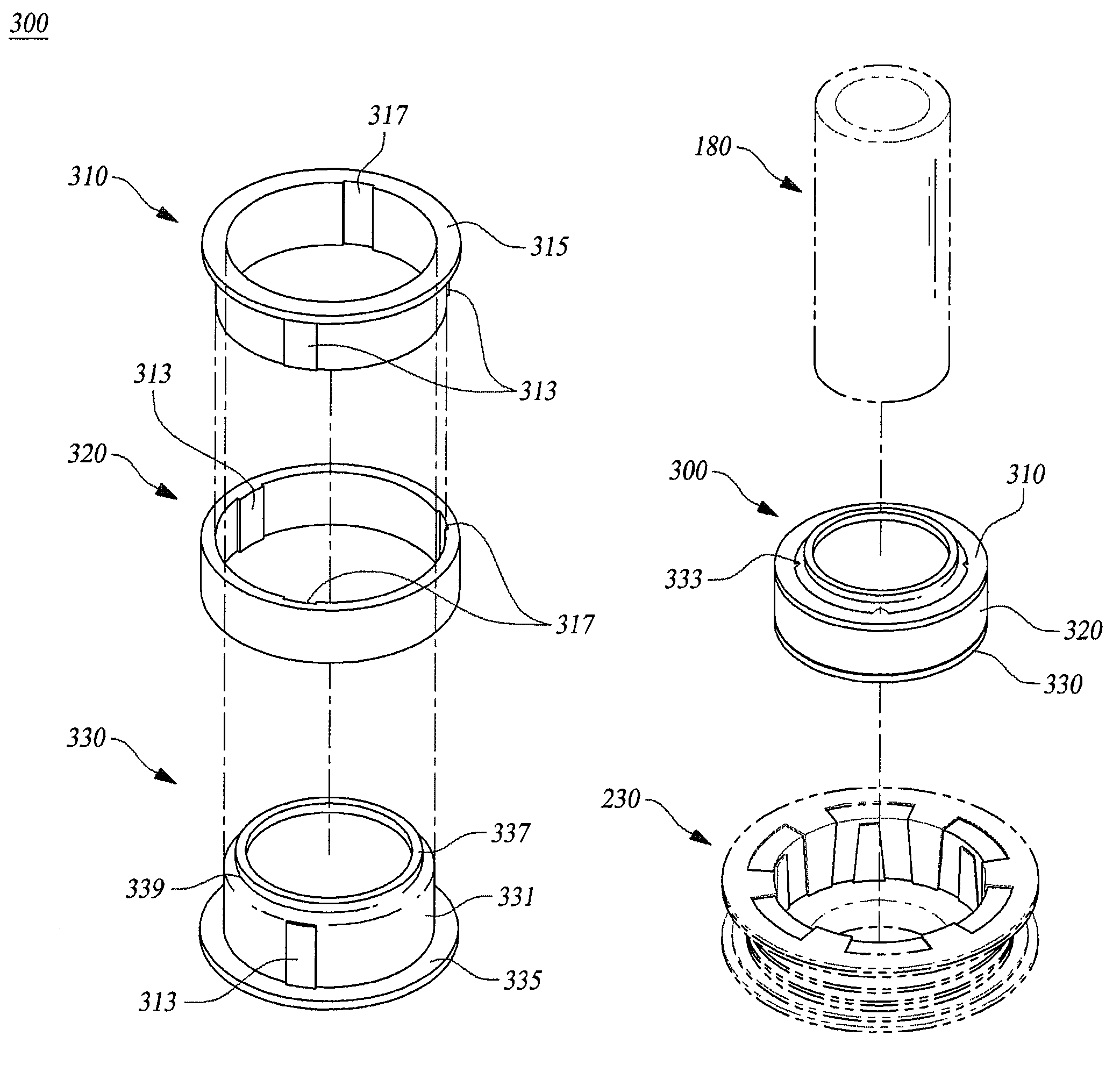
The present invention provides a torque rotor and a method for manufacturing it that can prevent inflow of plastic between a yoke and a magnet during a conventional plastic injection molding process, which prevents degradation of a roundness of the magnet or damage of the magnet due to the difference in temperature expansion coefficients and prevents idle rotation of the yoke and the magnet relative to each other. This results in a higher quality torque rotor and improved performance.

Problems solved by technology

At this time, the plastic is flowed in the yoke and the magnet so that a roundness of the magnet is deteriorated, thereby incurring a problem of generation of magnetic field declination between the magnet and position rotor.
Further, the assembling of the yoke and the magnet is not stable so that the yoke and the magnet are idling relative to each other by shock or a difference of a coefficient of temperature expansion, thereby incurring a serious problem of generation of an error of a torque measurement value or the magnet breakage.

Method used


Image

  • Torque rotor and method for manufacturing the same
  • Torque rotor and method for manufacturing the same
  • Torque rotor and method for manufacturing the same

Examples


Embodiment Construction

[0036]Hereinafter, preferred embodiments of the present invention will be described with reference to the accompanying drawings. In the following description, the same elements will be designated by the same reference numerals although they are shown in different drawings. In the following description, detailed explanation of known related functions and constitutions may be omitted to avoid unnecessarily obscuring the subject manner of the present invention.

[0037]Further, a term of a first, a second, A, B, (a), (b), and the like may be used for describing a constructional element of the present invention. Such a term is only for discriminating the corresponding constructional element from another constructional element, but does not limit a nature, a sequence, or an order of the corresponding constructional element. If it is described that a constructional element is “linked”, “assembled”, or “connected” with another constructional element, the constructional element may be directly...


PUM

PropertyMeasurementUnit
magnetic forceaaaaaaaaaa
areaaaaaaaaaaa
circumferenceaaaaaaaaaa

Abstract

Disclosed is a torque rotor and method for manufacturing the torque rotor having an effect of preventing inflow of plastic between a yoke and a magnet during a conventional plastic injection molding process for forming an assembling structure after assembling between the yoke and the magnet, thereby preventing degradation of a roundness of the magnet or damage of the magnet due to the difference in the temperature expansion coefficients, and preventing idle rotation of the yoke and the magnet relative to each other.

Description

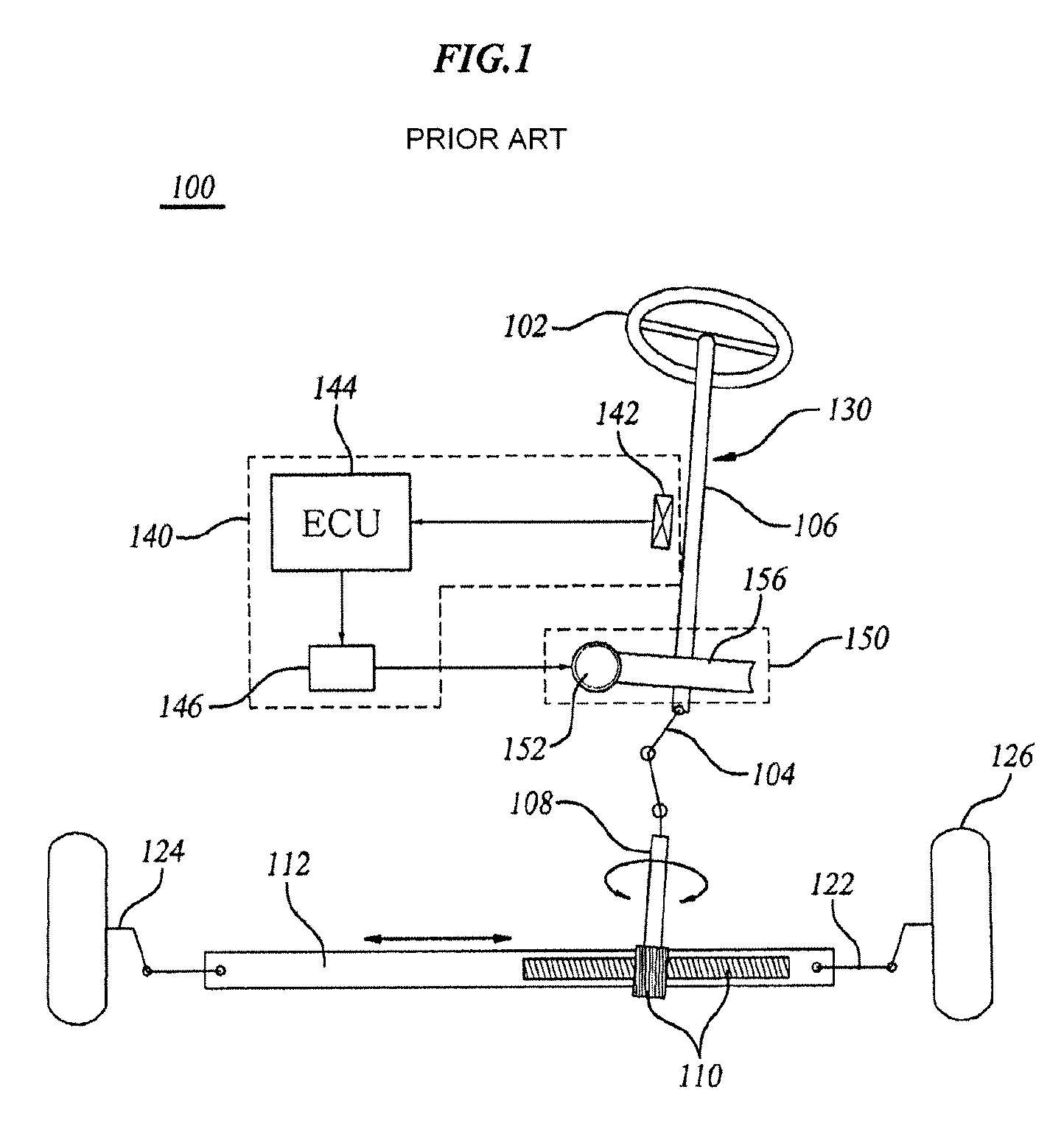
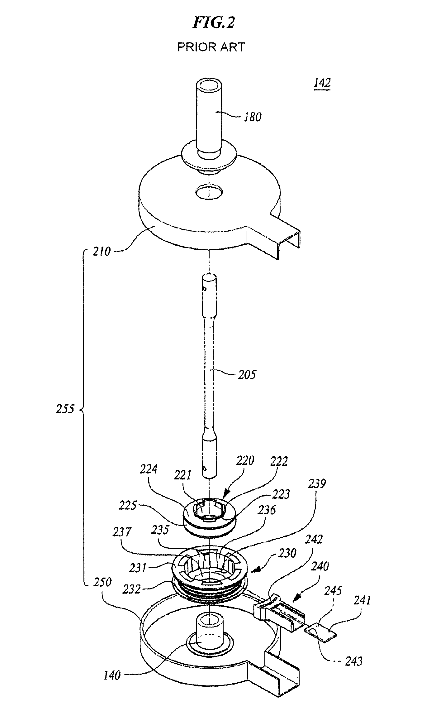
BACKGROUND OF THE INVENTION[0001]1. Field of the Invention[0002]The present invention relates to a torque rotor. More particularly, the present invention relates to a torque rotor and a method for manufacturing the torque rotor, which can prevent inflow of plastic between a yoke and a magnet during a conventional plastic injection molding process for forming an assembling structure after assembling between the yoke and the magnet, thereby preventing degradation of a roundness of the magnet or damage of the magnet due to the difference in the temperature expansion coefficients, and preventing idle rotation of the yoke and the magnet relative to each other.[0003]2. Description of the Prior Art[0004]A vehicle generally uses a power steering apparatus serving as a means for reducing steering power of a steering wheel (handle) and guaranteeing the stability of a steering state. In this respect, a conventional Hydraulic Power Steering system (HPS) using hydraulic pressure has been widely ...

Claims


Application Information

Patent Timeline
Patent Type & Authority Patents(United States)
IPC IPC(8): H02K1/27
CPCH02K15/03H02K15/12Y10T29/49012H02K37/18B62D6/10B62D5/04B62D6/00
Inventor KIM, CHAE-SOO
Owner HL MANDO CORP
Learn More