
Multibundle metal fiber yarn

a metal fiber yarn and multi-bundle technology, applied in the field of continuous metal fibers, can solve the problems of negative effect on the flexibility prone to sleeving of spiral winding around the outer circumference of a polyamide fiber core, and expected and desired increase of the strength of metal fiber yarn, so as to achieve no loss of flexibility

Inactive Publication Date: 2013-07-02
NV BEKAERT SA
View PDF30 Cites 1 Cited by
  • Summary
  • Abstract
  • Description
  • Claims
  • Application Information

AI Technical Summary

Benefits of technology

[0009]An aspect of the claimed invention provides a metal fiber yarn which comprises at least 5 bundles of continuous metal fibers twisted together to form a yarn. Each of the metal fiber bundles comprises at least 30 metal fibers. The yarn comprises at least one partial yarn. A partial yarn comprises at least two of said at least 5 metal fiber bundles twisted around each other with a predetermined number of torsions per meter. This provides a new type of continuous metal fiber yarn which is more stable, with no loss of flexibility.
[0011]More preferably identical partial yarns, being partial yarns comprising the same amount of metal fiber bundles, the same amount of metal fibers over a cross section, with the same amount of torsions per meter and the same torsion direction, are twisted around each other with a predetermined number of torsions per meter. This provides an even more stable metal fiber yarn.
[0012]In an alternative preferred embodiment, at least on of the at least two partial yarns has differing number of torsions per meter, and is twisted together with a same or different) predetermined number of torsions per meter to form the yarn of the invention. Such a yarn construction provides a combination of strength (of the more closed partial yarns) and an open structure (of the more open, less torded partial yarns). The open structure allowing polymer penetration of the continuous metal fiber yarn of the invention. The open structure allowing also a higher air permeability when the metal fiber yarn is produced into textiles, such as by knitting or weaving.
[0013]In one preferred embodiment the torsion direction of the partial yarns is opposite to the torsion direction of the yarn. This is what is called in the art S and Z twist. By using opposite twists in the partial and final yarn, the yarn structure will be more open allowing better polymer adhesion by the increased contact surface. In another preferred embodiment the torsion direction of the partial yarns is the same as the torsion direction of the final yarn. This embodiment results in a compact yarn with a high strength and good processability. In an even more preferred embodiment the torsions and torsion directions of the partial yarns and final yarn are the same and the amount of metal fiber bundles within the partial yarns and the amount of fibers per bundle are the same, thereby obtaining a yarn wherein the individual bundles all have substantially the same length. This results in a yarn with a high strength and large elongation.

Problems solved by technology

Increasing the amount of metal fibers per bundle in the yarn has, however, a negative effect on the flexibility of the metal fiber yarn.
However, this spirally winding around the outer circumference of a polyamide fiber core is prone to sleeving.
Using more metal fiber bundles in the yarn has proven to be limited, i.e. an increase in the amount of metal fiber bundles, did not result in the expected and desired increase of the strength of the metal fiber yarn.
It was further noted that an increase in the amount of metal fiber bundles in the yarn also increased the occurrence of sleeving or decomposition of the yarn resulting in bad processability of the yarn, especially when the metal fiber yarns are made through bundled drawing followed by yarn construction on composite level.
When such sleeving sensitive metal fiber yarn is used during subsequent processing, congestion in guiding parts or on small passages may occur.
The smaller than expected increase in breaking force of the yarns consisting out of 5 or more continuous metal fiber bundles occurring together with an increase in the sleeving phenomenon, made people in the art conclude that using 5 or more metal fiber bundles in a yarn was not favourable.

Method used


Image

  • Multibundle metal fiber yarn
  • Multibundle metal fiber yarn
  • Multibundle metal fiber yarn

Examples


Embodiment Construction

[0043]Examples of metal fiber yarns and different methods for obtaining the metal fiber yarn of the invention will now be described with reference to the Figures.

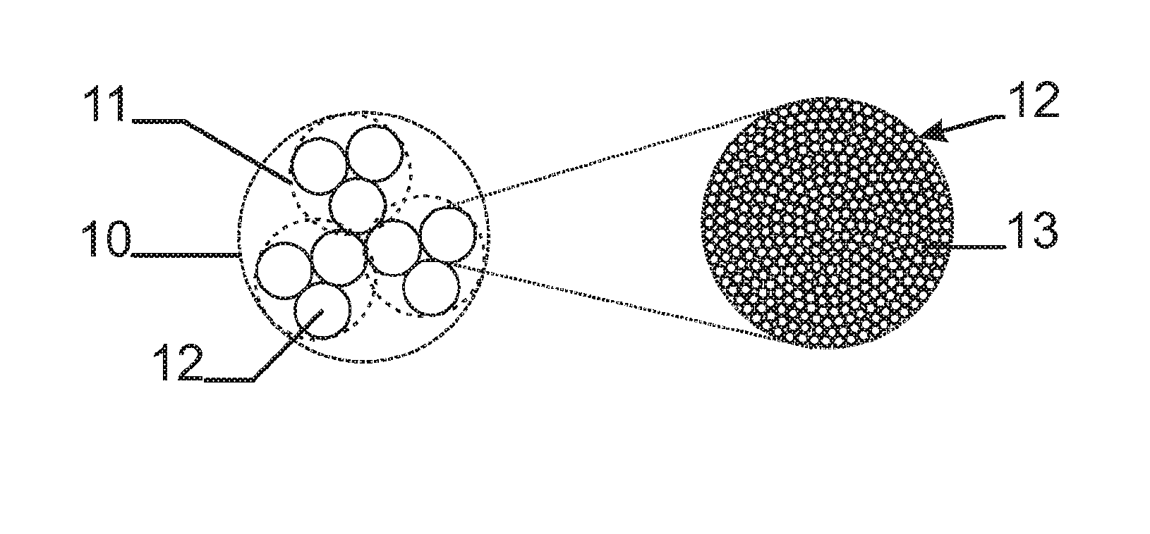
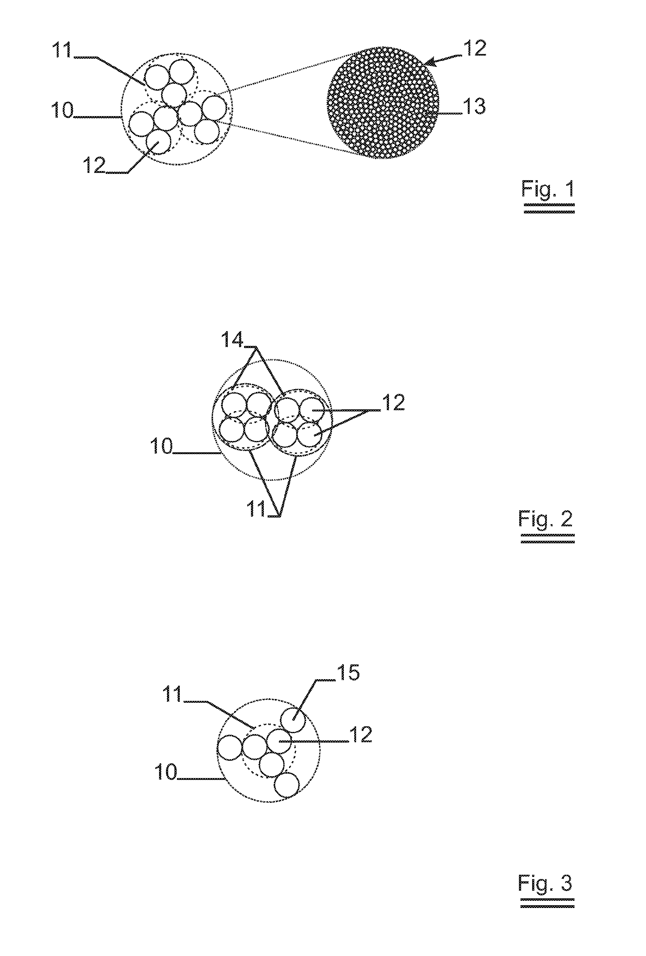
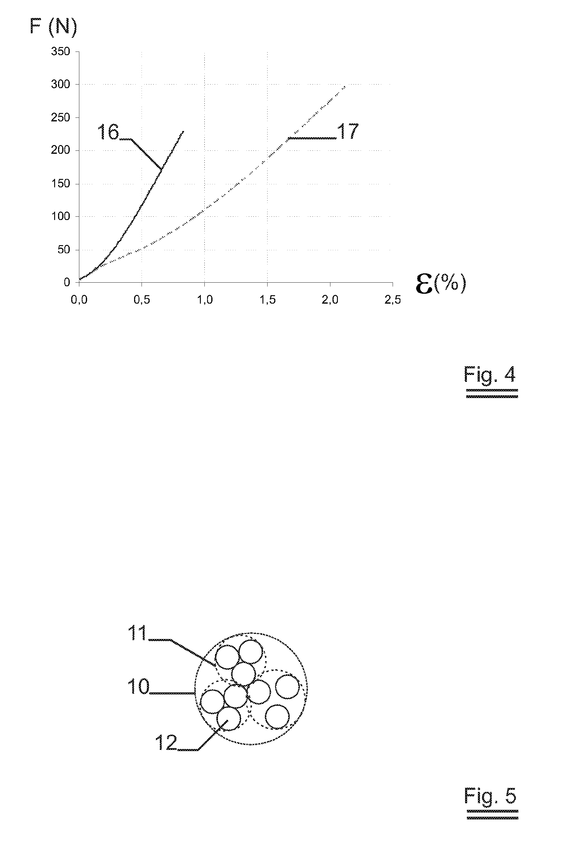
[0044]FIG. 1 shows the transverse cross section of a 3×3 yarn. The final yarn 10 comprises 3 partial yarns 11 twisted around each other. The partial yarns 11 comprise 3 continuous metal fiber bundles 12 twisted around each other. Each fiber bundle comprises 90 continuous metal fibers 13. This yarn is produced in two steps.

[0045]FIG. 2 shows the transverse cross section of a 2×2×2 yarn. The final yarn 10 consists out of 2 partial yarns 11 twisted around each other. Each partial yarn 11 comprises 2 first partial yarns 14 twisted around each other. Each first partial yarn 14 comprises 2 continuous metal fiber bundles 12 twisted around each other and each fiber bundle comprises 275 continuous metal fibers 13. This yarn is produced in 3 steps.

[0046]FIG. 3 shows the transverse cross section of a (3×1)+3 yarn. The final yarn 10 co...


PUM

PropertyMeasurementUnit
equivalent diameteraaaaaaaaaa

Abstract

A new metal fiber yarn is provided. The metal fiber yarn (10) constitutes a construction comprising continuous metal fibers (13) forming a metal fiber yarn. The construction comprises at least 5 bundles (12) of continuous metal fibers twisted together to form a yarn. Each of the metal fiber bundles (12) comprises at least 30 metal fibers (13). The yarn comprises at least one partial yarn (11), said partial yarn comprising at least two metal fiber bundles (13) twisted around each other with a predetermined number of torsions per meter.

Description

TECHNICAL FIELD[0001]The present invention relates to continuous metal fibers and bundles of continuous metal fibers, e.g. obtained by the bundled drawing of wires. More specifically, the present invention relates to high quality metal fiber yarns and methods of producing these metal fiber yarns.BACKGROUND ART[0002]Metal fiber bundles can be obtained in various ways. Metal fibers can be obtained by a method of bundled drawing as described e.g. U.S. Pat. No. 3,379,000.Metal fibers can also be obtained e.g. by drawing till final diameter, also called end drawing. Typically, metal fibers are less than 60 μm in equivalent diameter. A metal fiber bundle is generally characterised as an array of parallel metal fibers. One type of metal fiber bundles include continuous metal fibers e.g. as obtained by bundled drawing or end drawing and combining these metal fibers into a bundle. Such metal fiber bundles can then be combined to produce metal fiber yarns. These yarns have properties such as ...

Claims


Application Information

Patent Timeline
Patent Type & Authority Patents(United States)
IPC IPC(8): D02G3/02
CPCD02G3/12D02G3/441D02G3/46H05B3/34H05B3/56H05B2203/017H05B2203/029H05B2203/033
Inventor LE PERCQ, LISADE BONDT, STEFAANTROOST, HENK
Owner NV BEKAERT SA
Learn More