
Traveling vehicle system and communication method in the traveling vehicle system

a communication method and vehicle technology, applied in vehicle position/course/altitude control, process and machine control, instruments, etc., can solve the problem that the system server cannot control the traveling vehicle in real time, and achieve the effect of preventing relative positions and efficient communication between the system server and the traveling vehicl

Active Publication Date: 2013-06-25
MURATA MASCH LTD
View PDF14 Cites 3 Cited by
  • Summary
  • Abstract
  • Description
  • Claims
  • Application Information

AI Technical Summary

Benefits of technology

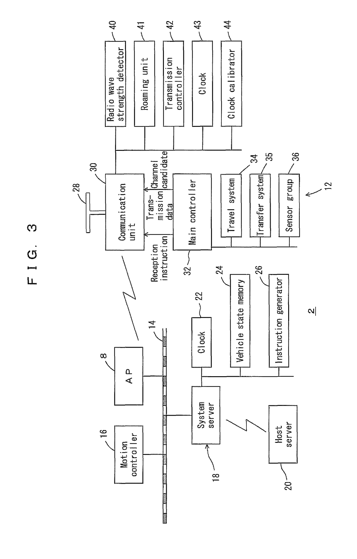
The invention allows communication between a system server and traveling vehicles to be efficient, regardless of delays in communication. It also allows traveling vehicles to quickly report their position to access points. The system server provides an instruction time zone and a report time zone for each control cycle. In the instruction time zone, traveling vehicles only transmit confirmation signals, while in the report time zone, they provide their position. This allows the system server to efficiently control the traveling vehicles through a wireless LAN. Multiple traveling vehicles can generate reports at the same time and execute instructions simultaneously, maintaining their relative positions. To prevent interference between reports, the report time zone is divided into time slots, and each traveling vehicle randomly selects one for reporting. This helps to determine the order of reports autonomously and reduces the likelihood of collision between reports.

Problems solved by technology

If the instructions or the reports are delayed, the system server cannot control the traveling vehicles in real time.

Method used


Image

  • Traveling vehicle system and communication method in the traveling vehicle system
  • Traveling vehicle system and communication method in the traveling vehicle system
  • Traveling vehicle system and communication method in the traveling vehicle system

Examples


Embodiment Construction

[0028]Hereinafter, preferred embodiments of the present invention will be described.

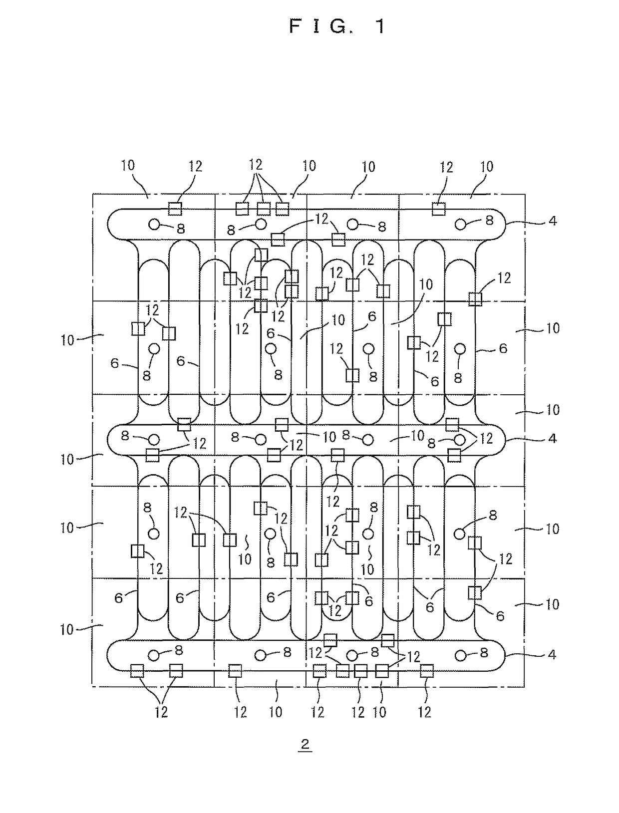
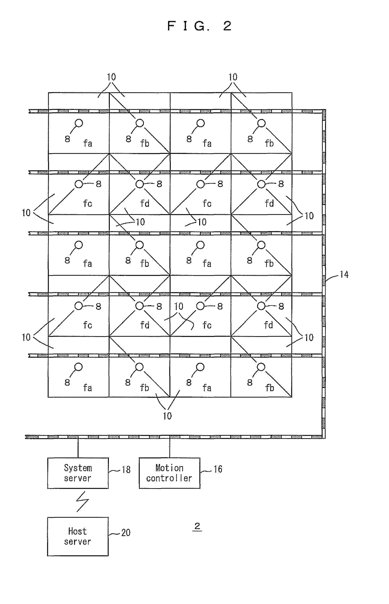
[0029]FIGS. 1 to 14 show a traveling vehicle system 2 according to a preferred embodiment of the present invention. FIG. 1 shows a layout of the system 2. Reference numerals 4 denote inter-bay routes each connecting a plurality of intra-bay routes 6. The entire routes 4, 6 are divided into about 10 to 50 portions of areas 10. An access point 8 is provided in each of the areas 10. The areas 10 are narrower in comparison with the communication capability of the access point 8. Specifically, the areas 10 are arranged such that each of traveling vehicles 12 can communicate with at least two access points 8 in any point on the travel routes 4, 6. In segments deviated from the normal travel route for transportation of articles, such as retraction segments and maintenance segments, the areas 10 may be arranged such that the traveling vehicle 12 can only communicate with one access point 8.

[0030]Reference nu...


PUM


Abstract

A system server and access points are connected through a LAN preferably on the ground. A control cycle is divided into an instruction time zone to provide instructions from the access points to traveling vehicles, and a report time zone to provide reports from the traveling vehicles to the access points. The access points transmit target positions in the instruction time zone, and the traveling vehicles report positions in the report time zone. The system server determines target positions based on the reported positions.

Description

BACKGROUND OF THE INVENTION[0001]1. Field of the Invention[0002]The present invention relates to a traveling vehicle system. In particular, the present invention relates to a system in which a large number of traveling vehicles are controlled by a system server through a wireless LAN.[0003]2. Description of the Related Art[0004]The applicant proposed a system in which a large number of traveling vehicles such as overhead traveling vehicles are controlled by a system server on the ground. See, for example, JP2008-150135A. In this system, the system server provides an instruction of a target position or the like for each traveling vehicle in each control cycle of, e.g., 0.1 s, for allowing the traveling vehicle to execute the instruction. A wireless LAN is used suitably for communication between the traveling vehicles and the system server. In this system, although the wireless LAN is used, it is important to ensure that the instructions from the system server to the traveling vehicle...

Claims


Application Information

Patent Timeline
Patent Type & Authority Patents(United States)
IPC IPC(8): G05D1/00G05D3/00G06F7/00G06F17/00
CPCG05D1/0287G05D2201/0213G05D1/0297G05D1/028
Inventor HORI, KIKUOOGAWA, TORUHIRAYAMA, HITOMIYAMANA, MASAYUKI
Owner MURATA MASCH LTD
Learn More