
Non-invasive physiological sensor cover

a sensor cover and physiological technology, applied in the field of sensors, can solve the problems of sensor exposure, sensor false reading, monitor alarm, etc., and achieve the effects of preventing or reducing false readings, preventing damage to the sensor, and reducing setup tim

Active Publication Date: 2013-06-25
MASIMO CORP
View PDF261 Cites 560 Cited by
  • Summary
  • Abstract
  • Description
  • Claims
  • Application Information

AI Technical Summary

Benefits of technology

[0005]Optical sensors are widely used across clinical settings, such as operating rooms, emergency rooms, post anesthesia care units, critical care units, outpatient surgery and physiological labs, to name a few. In some situations, such as in operating rooms, emergency rooms or critical care units, sensors can be kept attached to monitors to reduce the setup time needed to begin monitoring a patient. While attached, the sensor can generate false readings by detecting ambient light even though the sensor is not in use. The sensor can also cause the monitor to emit alarms or otherwise make noise due to false readings, which can be distracting to medical personnel.
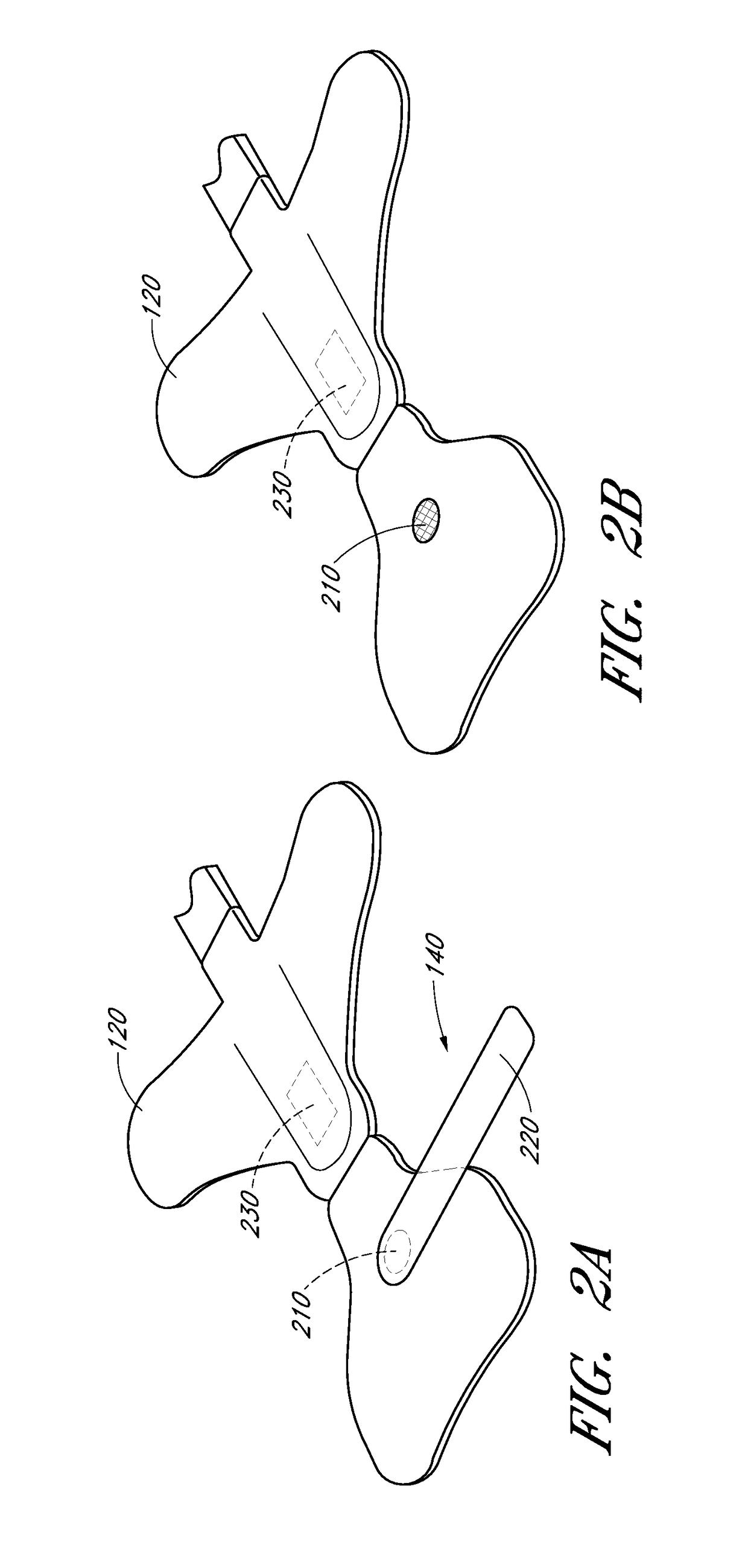
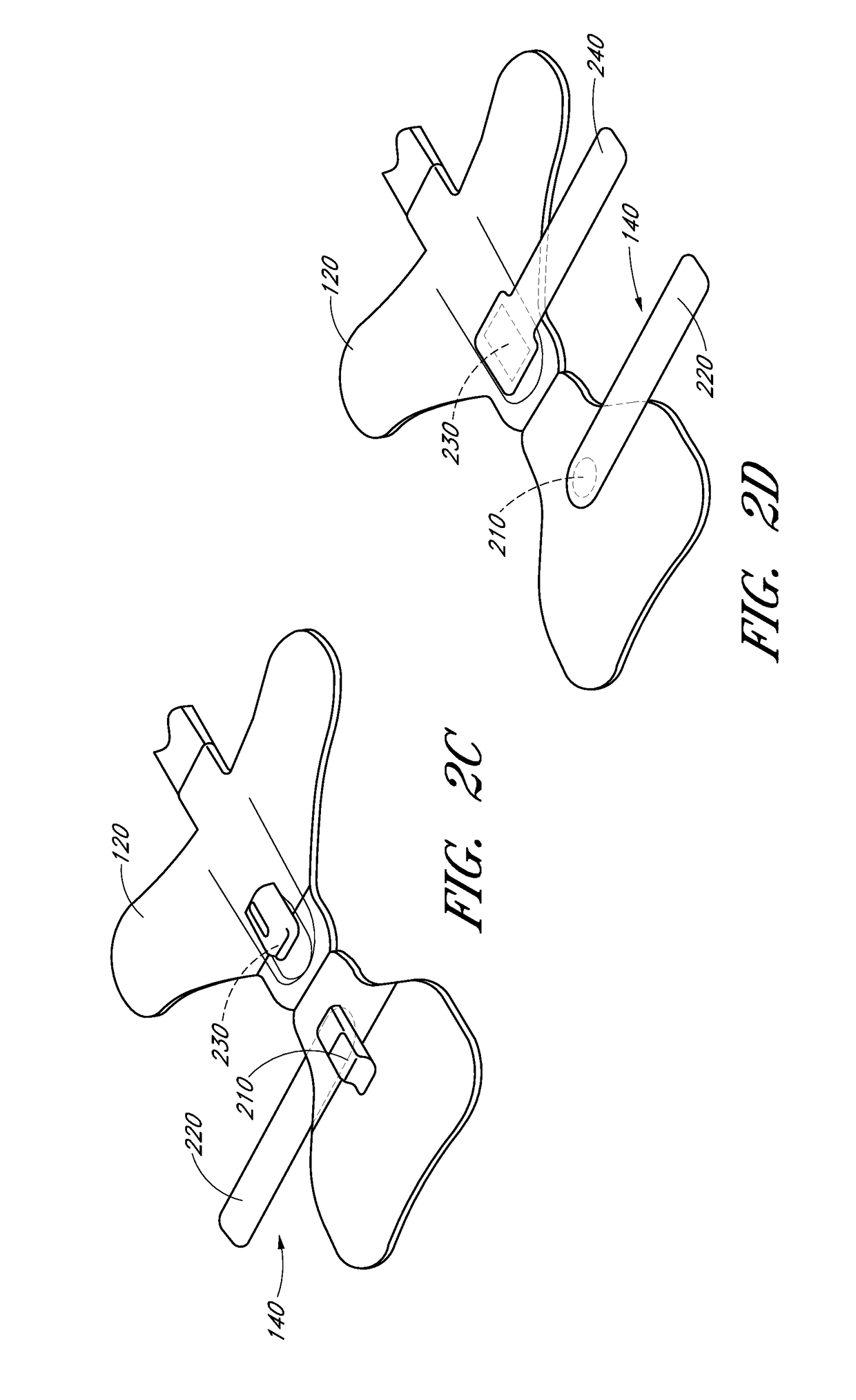
[0006]As such, a method and apparatus for preventing false readings are desirable. A sensor cover, according to embodiments of the disclosure, prevents or reduces false readings until the sensor is in use.
[0007]Further, in certain embodiments, the sensor cover can prevent damage to the sensor. For example, the sensors cover can protect the emitters and the detector during shipment or prior to use. In certain embodiments, a sensor cover decreases the likelihood of contamination by keeping covered portions of the sensor clean. Sensors in hospitals and other clinical environments are subject to exposure to infectious agents, dust or other foreign matter from depositing on the emitters or detector. The sensor cover can reduce or prevent exposure to these contaminants.

Problems solved by technology

While attached, the sensor can generate false readings by detecting ambient light even though the sensor is not in use.
The sensor can also cause the monitor to emit alarms or otherwise make noise due to false readings, which can be distracting to medical personnel.
Sensors in hospitals and other clinical environments are subject to exposure to infectious agents, dust or other foreign matter from depositing on the emitters or detector.

Method used


Image

  • Non-invasive physiological sensor cover
  • Non-invasive physiological sensor cover
  • Non-invasive physiological sensor cover

Examples


Embodiment Construction

[0024]A sensor cover according to embodiments of the disclosure is capable of being used with a non-invasive physiological sensor. Certain embodiments of the sensor cover reduce or eliminate false readings from the sensor when the sensor is not in use. Further, embodiments of the sensor cover can prevent damage to the sensor. Additionally, embodiments of the sensor cover prevent contamination of the sensor.

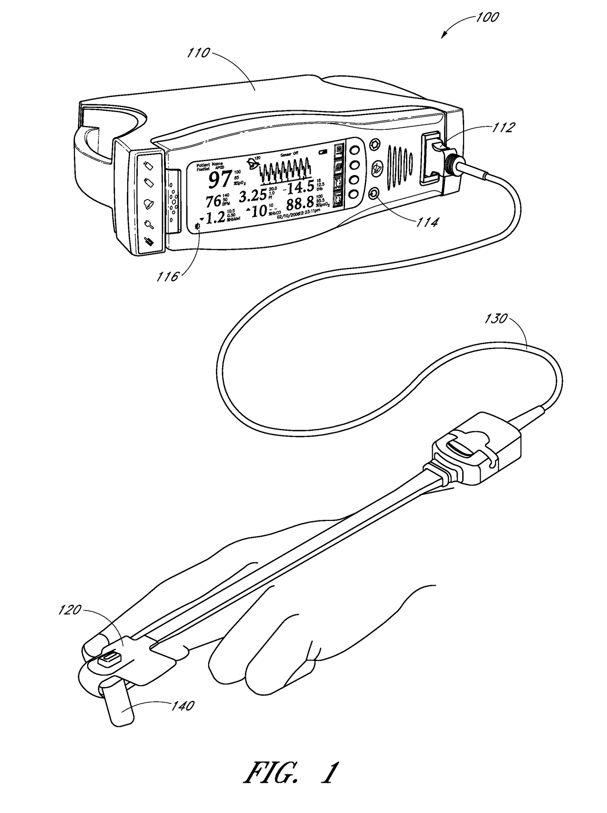
[0025]The tissue site of the illustrated embodiments is a finger and the following description therefore refers specifically to the tissue site as a finger for the purposes of clarity. This is not intended to be limiting and, as described herein, the sensor cover of certain embodiments can be used with sensors attachable to other types of tissue sites, such as a toe, ear lobe, nose, hand, foot, forehead or the like.

[0026]FIG. 1 illustrates an embodiment of a sensor cover attached to a physiological measurement system 100 having a monitor 110 and an optical sensor 120. The optical ...


PUM


Abstract

A sensor cover according to embodiments of the disclosure is capable of being used with a non-invasive physiological sensor, such as a pulse oximetry sensor. Certain embodiments of the sensor cover reduce or eliminate false readings from the sensor when the sensor is not in use, for example, by blocking a light detecting component of a pulse oximeter sensor when the pulse oximeter sensor is active but not in use. Further, embodiments of the sensor cover can prevent damage to the sensor. Additionally, embodiments of the sensor cover prevent contamination of the sensor.

Description

CROSS-REFERENCE TO RELATED APPLICATIONS[0001]The present application claims priority benefit under 35 U.S.C. §119(e) from U.S. Provisional Application No. 61 / 229,682, filed Jul. 29, 2009, entitled “Non-invasive Physiological Sensor Cover,” which is incorporated herein by reference in its entirety.FIELD OF THE DISCLOSURE[0002]The present invention relates to a sensor for measuring oxygen content in the blood, and, in particular, relates to an apparatus and method for preventing sensor activity when the sensor is not in use.BACKGROUND OF THE DISCLOSURE[0003]Non-invasive physiological sensors are applied to the body for monitoring or making measurements indicative of a patient's health. One application for a non-invasive physiological sensor is pulse oximetry, which provides a noninvasive procedure for measuring the oxygen status of circulating blood. Oximetry has gained rapid acceptance in a wide variety of medical applications, including surgical wards, intensive care and neonatal un...

Claims


Application Information

Patent Timeline
Patent Type & Authority Patents(United States)
IPC IPC(8): A61B5/02
CPCA61B5/14552A61B5/6838A61B5/6826A61B5/68335A61B5/6832A61B2562/185A61B5/02416A61B5/14532A61B5/14546A61B5/6816A61B5/6819A61B5/6829A61B5/02427
Inventor KIANI, ABRAHAM MAZDAKIANI, MASSI JOE E.
Owner MASIMO CORP
Learn More