
Controlled load regulation and improved response time of LDO with adaptive current distribution mechanism

a load regulation and adaptive current technology, applied in the direction of electric variable regulation, process and machine control, instruments, etc., can solve the problems of increasing the cost of capacitors, and requiring a large amount of board spa

Active Publication Date: 2013-06-25
SANDISK TECH LLC
View PDF20 Cites 14 Cited by
  • Summary
  • Abstract
  • Description
  • Claims
  • Application Information

AI Technical Summary

Problems solved by technology

However, this increases the cost of this capacitor and it needs the board area.
In many applications, this needed increase in board area can be very difficult to come by.
Although this again helps to separate the poles, it is done at the cost of increased quiescent current of the LDO for all loads.
As both of these approaches have drawbacks, there is consequently room for improvement in the design of low drop out regulation circuits.

Method used


Image

  • Controlled load regulation and improved response time of LDO with adaptive current distribution mechanism
  • Controlled load regulation and improved response time of LDO with adaptive current distribution mechanism
  • Controlled load regulation and improved response time of LDO with adaptive current distribution mechanism

Examples


Embodiment Construction

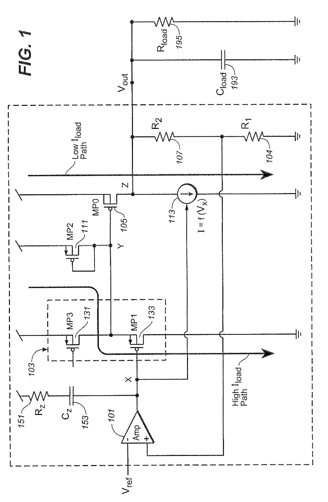
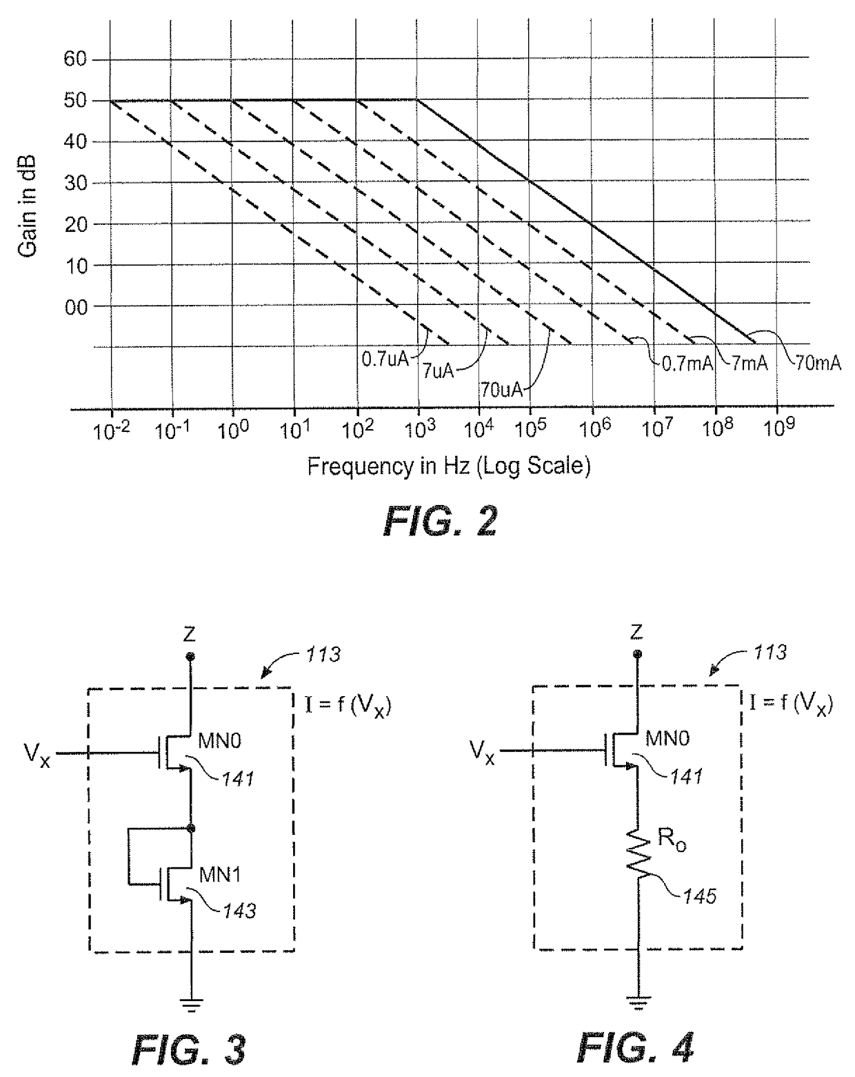
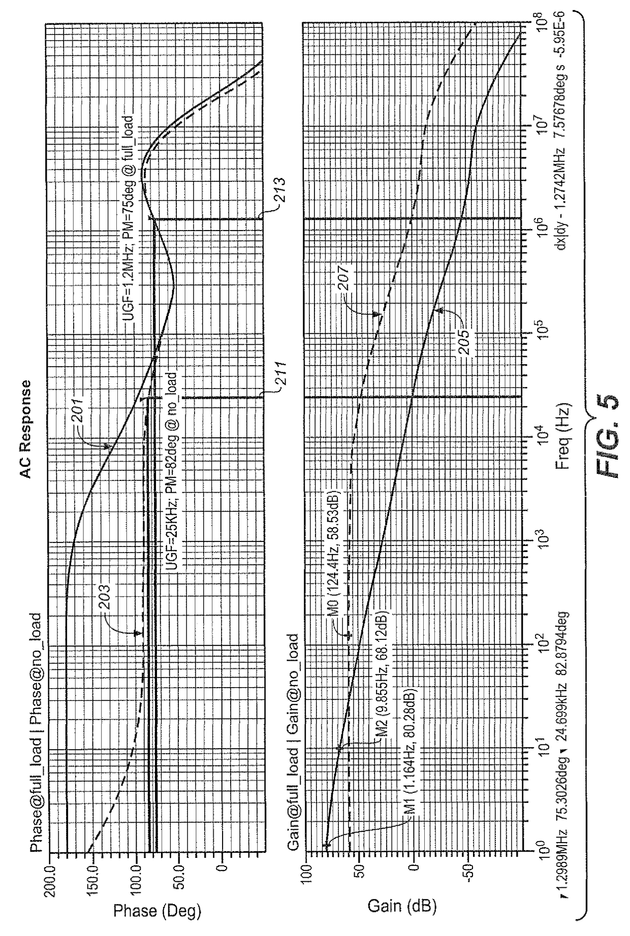
[0011]The techniques presented in the following provide a low drop-out (LDO) voltage regulation circuit that improves upon many of the limitations described above in the Background section. In particular, the load regulation in the exemplary embodiment of an LDO will improve as the DC gain will not go down at lower load currents. Further, the no load to full load response time is improved as the load pole and power MOS gate pole are actively controlled with respect to output load current. In this mechanism, as the amount of current being supplied to the load decreases, the internal current flow shifts from a first internal current path to a second internal current path and vice versa. This arrangement maintains the desired pole structure and keeps the quiescent current largely the same for all load current levels.

[0012]More specifically, FIG. 1 is an exemplary embodiment to illustrate some aspects. Relative to a typical implementation of an LDO regulator, the mechanism presented her...


PUM


Abstract

A low drop-out (LDO) voltage regulation circuit includes first and second internal current paths. The first internal current path is between the input supply voltage and ground and includes the regulator's buffer circuit. The second internal current path is between the input supply voltage and ground and includes the regulator's power transistor. The amount of current flowing through the first internal current path relative to the amount of current flowing through the second internal current path is an increasing function of a current supplied to a load connected to the output supply node. The load regulation of the LDO is improved as the DC gain will not go down at lower load currents. Further, the no load to full load response time is improved as the load pole and power MOS gate pole are actively controlled with respect to output load current. In this mechanism, as the amount of current being supplied to the load decreases, the internal current flow shifts from the first internal current path to the second internal current path and vice versa. This arrangement maintains the desired pole structure and keeps the quiescent current largely the same for all load current levels.

Description

FIELD OF THE INVENTION[0001]This invention pertains generally to the field of voltage regulation circuits and, more particularly, to low drop out (LDO) regulators and controlling the regulation of their load.BACKGROUND[0002]Voltage regulation circuits have many applications in power supply systems to provide a regulated voltage at a predetermined multiple of a reference voltage. In low drop-out regulator designs, there commonly occur two poles at lower frequencies, one due to the output impedance of the circuit's power MOS transistor together with load capacitor and another due to the gate capacitance of the power MOS with impedance connected to this node. These two poles come very close to each other in many designs. One way to separate these poles is to increase the value of a load capacitor, so as to move the load pole towards the lower frequencies. However, this increases the cost of this capacitor and it needs the board area. In many applications, this needed increase in board ...

Claims


Application Information

Patent Timeline
Patent Type & Authority Patents(United States)
IPC IPC(8): G05F1/00
CPCG05F1/575
Inventor PANCHOLI, DEEPAKODEDARA, BHAVINPRASAD, NAIDU
Owner SANDISK TECH LLC
Learn More