
Multiple parameter fault detection in electrosurgical instrument shields

a multi-parameter, shield technology, applied in the field of multi-parameter fault detection in electrosurgical instrument shields, can solve the problems of difficult more sophisticated monitoring techniques, limited detection of shield faults, and not providing a great deal of flexibility to surgeons

Active Publication Date: 2013-06-11
ENCISION INC
View PDF69 Cites 120 Cited by
  • Summary
  • Abstract
  • Description
  • Claims
  • Application Information

AI Technical Summary

Benefits of technology

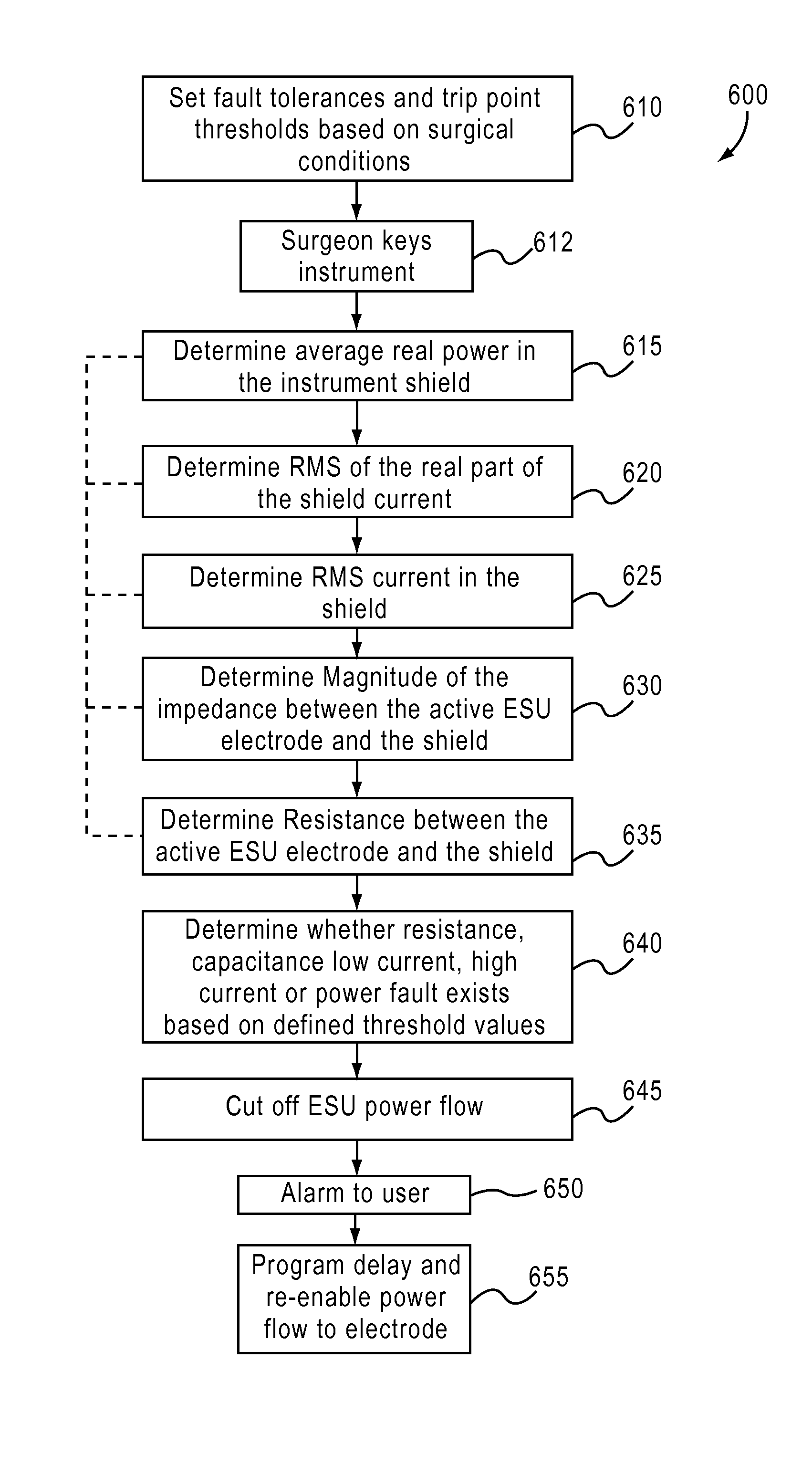
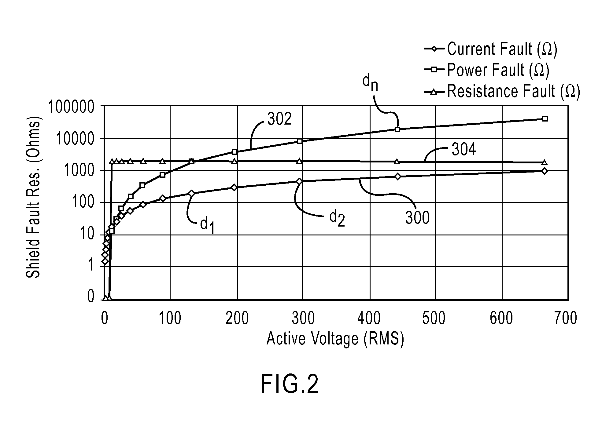
The patent describes a system for detecting faults in an electrosurgical instrument. The system includes monitoring circuitry that measures various factors such as active voltage, current, and shield current. This monitoring circuitry can detect a variety of faults, such as resistance, high-current, low-current, capacitance, and power failure. The system is able to detect these faults in real-time, allowing for timely maintenance and repair of the electrosurgical instrument. Overall, this system improves the reliability and accuracy of electrosurgical procedures.

Problems solved by technology

Furthermore, existing systems rely heavily on analog circuits and associated monitoring techniques that result in limitations in how the existence of a shield fault is detected, communicated to a user, and delivered to the ESU for deactivation.
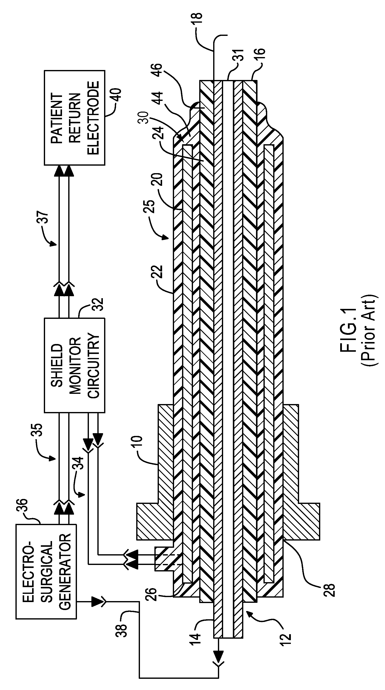
As can be appreciated by those of skill in the art, the prior art as described herein only provides the ability to detect a fault condition based on sensing the current in the shield and thus does not provide a great deal of flexibility to the surgeon to account for the use of modern electrosurgical instruments and varying surgical procedures that might benefit from a monitoring device that is capable of detecting faults based on other radio frequency parameters.
In addition, the limitations imposed by the use of analog sensing electronics and associated processing schemes make more sophisticated monitoring techniques difficult and make it more difficult to customize the fault detection process for varying situations where one fault threshold may not be adequate or appropriate.

Method used


Image

  • Multiple parameter fault detection in electrosurgical instrument shields
  • Multiple parameter fault detection in electrosurgical instrument shields
  • Multiple parameter fault detection in electrosurgical instrument shields

Examples


Embodiment Construction

[0018]While the prior art has been described in the context of a rigid laparoscopic instrument, it should be understood that aspects of the present invention may be utilized in conjunction with a variety of types and designs of shielded surgical instruments and other tools. For example, electrosurgical instruments employing flexible tubing and those instruments utilizing a generally larger diameter tubular shaft, such as hysteroscopic instruments described in e.g. U.S. Pat. No. 7,422,589, commonly assigned to Encision, Inc., may also be used in conjunction with aspects of the present invention. U.S. Pat. No. 7,422,589 describes alternative referencing for the instrument shield connection other than a direct connection to the return electrode. Such connections are possible for each of the measuring techniques described herein.

[0019]In general terms, aspects of the present invention relate to an improved method of detecting faults in, for example, the shields of electrosurgical instru...


PUM


Abstract

A system and method for detecting faults within an electrosurgical instrument having a shield and an active electrode uses multiple possible fault conditions. In one embodiment the monitoring system comprises an electrosurgical generator coupled to the electrosurgical instrument and adapted to deliver power to the active electrode of the electrosurgical instrument, monitoring circuitry coupled to the electrosurgical generator and the electrosurgical instrument, wherein the monitoring circuitry comprises an active electrode voltage sensor an active electrode current sensor and a shield current sensor. The monitoring circuitry measures at least two of the active voltage, the active or return electrode current, and the shield current.

Description

PRIORITY AND RELATED APPLICATIONS[0001]This application claims the benefit of Provisional U.S. Patent Application No. 60 / 982,990 filed on Oct. 26, 2007. The details of this Application No. 60 / 982,990 are incorporated by reference into the present application in its entirety and for all purposes.FIELD OF THE INVENTION[0002]Aspects of the present invention relate to devices and methods for the detection of faults in electrosurgical instruments powered by electrosurgical units (ESU). More particularly, aspects of the present invention relate to the monitoring and use of multiple radio frequency parameters in order to more particularly and specifically control the delivery of electrosurgical current during a surgical procedure.BACKGROUND[0003]The method used in predicate systems for detecting faults in the shields of electrosurgical instruments is sensitive only to the current in the shield. Furthermore, existing systems rely heavily on analog circuits and associated monitoring techniqu...

Claims


Application Information

Patent Timeline
Patent Type & Authority Patents(United States)
IPC IPC(8): A61B18/12
CPCA61B18/1233A61B18/1206A61B18/16A61B2018/00708A61B2018/00875A61B2018/00648A61B2018/00672A61B2018/00702A61B2018/00779A61B2018/00827A61B2018/00892
Inventor ARONOW, KURT ALBERTNEWTON, DAVIDBOYLE, DON R.
Owner ENCISION INC
Learn More