
Endotracheal tube with intrinsic suction and endotracheal suction control valve

a technology of intrinsic suction and endotracheal suction control, which is applied in the field of endotracheal tubes, can solve the problems of team personnel's risk, bleeding or other interference with surgical maneuvers, and achieve the effects of effective attack, convenient administration of intratracheobronchial medications, and accurate placement of tubes

Inactive Publication Date: 2013-06-04
BLACK PAUL WILLIAM +1
View PDF0 Cites 9 Cited by
  • Summary
  • Abstract
  • Description
  • Claims
  • Application Information

AI Technical Summary

Benefits of technology

The improved specialized endotracheal tube allows for the removal of accumulated secretions above the cuff outside the tube and within the tracheobronchial system. This makes it easier to use with an endoscope and videolaryngoscopy to assist in insertion through the vocal cords and accurate placement of the tube in difficult cases. The new revisions also provide for ease of administration of intratracheobronchial medications, and the suction and medication functions are accomplished with a closed system to reduce the possibility of contamination. The method also involves directly administering medicine into the tracheobronchial system and placing a flexible endoscope for videolaryngoscopy to assist in accurate passage of the endotracheal tube.

Problems solved by technology

During general anesthesia the gasses introduced through the endotracheal tube and the tube itself create irritation in the tracheobronchial system resulting in secretions that must be suction removed periodically by the anesthesiologist to clear the airway.
Thus, the flow of essential gasses to the patient is temporarily interrupted and some gasses undesirably escape into the operating room air breathed by the operating team, which can present a risk to the team personnel.
Furthermore, the movement of the endotracheal tube and the insertion of yet another foreign object, the conventional suction tube itself, often stimulates involuntary patient muscle contractions and movements which can cause bleeding or otherwise interfere with surgical maneuvers.

Method used


Image

  • Endotracheal tube with intrinsic suction and endotracheal suction control valve
  • Endotracheal tube with intrinsic suction and endotracheal suction control valve
  • Endotracheal tube with intrinsic suction and endotracheal suction control valve

Examples


Embodiment Construction

[0056]In describing the preferred and other embodiments of the technology described herein, as illustrated in FIGS. 1-10, specific terminology is employed for the sake of clarity. The invention, however, is not intended to be limited to the specific terminology so selected, and it is to be understood that each specific element includes all technical equivalents that operate in a similar manner to accomplish similar functions.

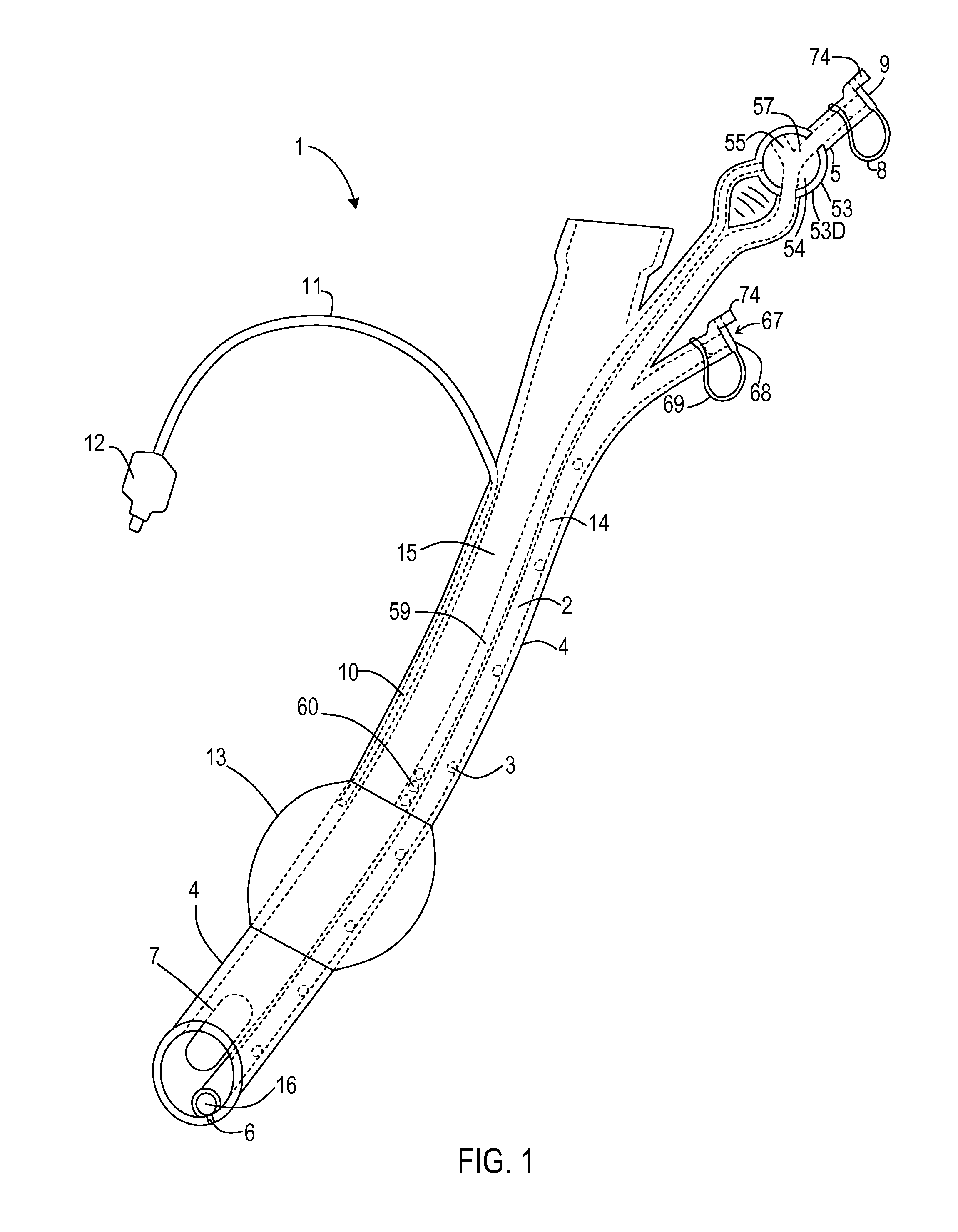
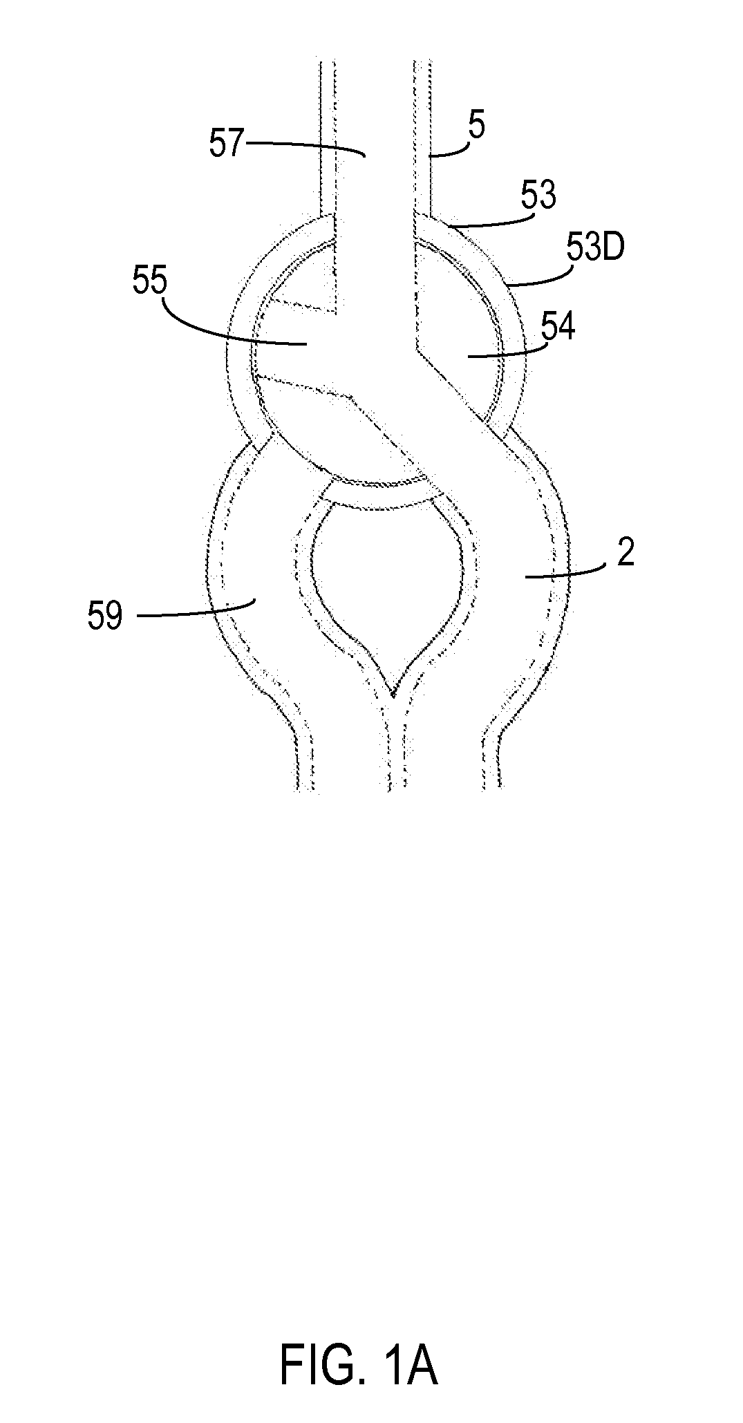
[0057]Referring now to FIG. 1 and FIGS. 2A, 2B, and 2C, illustrated therein is an embodiment of an improved endotracheal tube with intrinsic suction. An outer tube 4 has an outer diameter that approximates the inner diameter of the passage to be intubated. A built in intrinsic suction channel 2 runs through the outer tube 4. The intrinsic suction channel 2 is integrally formed within the lumen of the outer tube 4. The intrinsic suction channel 2 spans from above the proximal end to the distal end of the outer tube 4 and has an opening 16 at the distal end. The d...


PUM


Abstract

An improved endotracheal tube providing a built in suction channel for the removal of excessive secretions from the lumen of said tube and the tracheobronchial system is disclosed. Control valves for regulating the suction feature are also disclosed. In at least one embodiment, the endotracheal tube includes an additional suction channel, an above-the-cuff suction channel adapted to remove secretions above the cuff outside the endotracheal tube and within the trachea. Additionally, in at least one embodiment, the endotracheal tube is configured for use with an endoscope for videolaryngoscopy, and the like. Furthermore, in at least one embodiment, an improved technology for the administration of medications within the tracheobronchial system is disclosed.

Description

CROSS-REFERENCE TO RELATED APPLICATION(S)[0001]This present non-provisional patent application is a continuation-in-part of copending U.S. patent application Ser. No. 11 / 855,995 filed on Sep. 14, 2007, and entitled “ENDOTRACHEAL TUBE WITH INTRINSIC SUCTION & ENDOTRACHEAL SUCTION CONTROL VALVE,” and of which the application cited above is incorporated in-full by reference herein.FIELD OF THE INVENTION[0002]The technology described herein relates generally to endotracheal tubes used for intubating the trachea and like opening of human and animal bodies.BACKGROUND OF THE INVENTION[0003]During general anesthesia the gasses introduced through the endotracheal tube and the tube itself create irritation in the tracheobronchial system resulting in secretions that must be suction removed periodically by the anesthesiologist to clear the airway.[0004]In the current conventional system, this requires detaching the gas delivery apparatus from the end of the endotracheal tube so a smaller suctio...

Claims


Application Information

Patent Timeline
Patent Type & Authority Patents(United States)
IPC IPC(8): A62B9/02
CPCA61M16/0463A61M16/0484A61M16/0434A61M16/0486
Inventor BLACK, PAUL WILLIAMMARTIN, LELIA MEADOWS
Owner BLACK PAUL WILLIAM
Learn More