
Display apparatus and control circuit of the same

a display apparatus and control circuit technology, applied in the field of image display devices, can solve the problems of unavoidable fluctuations in gamma characteristic, large electrical power consumption of backlighting, and rise of entire backlight luminance, so as to reduce power consumption, reduce uneven or irregular sections, and high light source luminance

Active Publication Date: 2013-05-28
MAXELL HLDG LTD
View PDF10 Cites 0 Cited by
  • Summary
  • Abstract
  • Description
  • Claims
  • Application Information

AI Technical Summary

Benefits of technology

[0012]Screen brightness in the liquid crystal display device is calculated as the product of the backlight brightness for each coordinate, and the transmittance rate of the liquid crystal element at the corresponding position. Area control lowers the power consumption by decreasing the luminance of each light source making up the backlight according to the image. Lowering the light source luminance also decreases the backlight luminance at each coordinate but the same luminance can be maintained by raising the transmittance of the liquid crystal element at corresponding positions. The transmittance between the input pixel value and liquid crystal element in a typical liquid crystal panel are related as shown in the following formula.Transmittance=gamma(pixel value)  (Formula 1)Here, y=gamma (x) is a function called the gamma function, and has characteristics approaching that of the power function. Taking advantage of this characteristic, the brightness of a certain coordinate before applying area control can be calculated by the following formula. Here the BL luminance is the backlight luminance.Screen brightness=gamma(pixel value)×BL luminance  (Formula 2)Expressing the screen brightness, pixel value, and BL luminance after applying area control by attaching an apostrophe' allows expressing the screen brightness after applying area control by the following formula.Screen brightness'=gamma(pixel value')×BL luminance'  (Formula 3)Exerting control so that the area control causes no change in screen brightness requires making the right sides of Formula 2 and Formula 3 equivalent. Changing the formula so that the right side of Formula 2 equals the right side of Formula 3 yields the following formula.Gamma(pixel value')=BL luminance / BL luminance'×gamma(pixel value)  (Formula 4)

Problems solved by technology

In display devices such as LCD that utilize backlighting without emitting their own light, the backlighting usually consumes most of the electrical power.
However if there is a luminescent spot on even just one point on the screen during global dimming, then the entire backlight luminance rises because the N value cannot be increased by this luminescent spot.
Fluctuations in the gamma characteristic however are unavoidable according to the viewing direction relative to the actual liquid crystal panel.
In this case, correcting the image based on the gamma characteristics when looking at the screen from the front may cause a strange impression if the screen is viewed from the side.
However, this method reduces the backlight fading rate which suppresses the effect that lowers power consumption.
Even in these images however, the processing reduces the backlight fading rate, which in turn suppresses the effect that cuts power consumption.

Method used


Image

  • Display apparatus and control circuit of the same
  • Display apparatus and control circuit of the same
  • Display apparatus and control circuit of the same

Examples


first embodiment

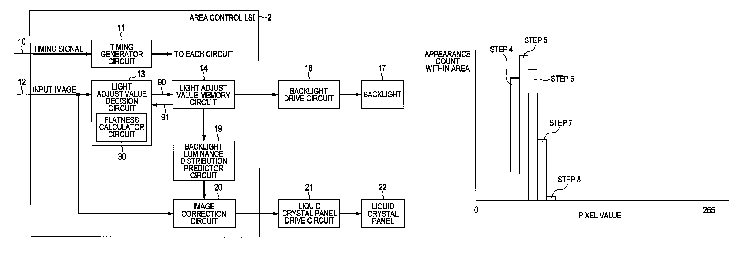
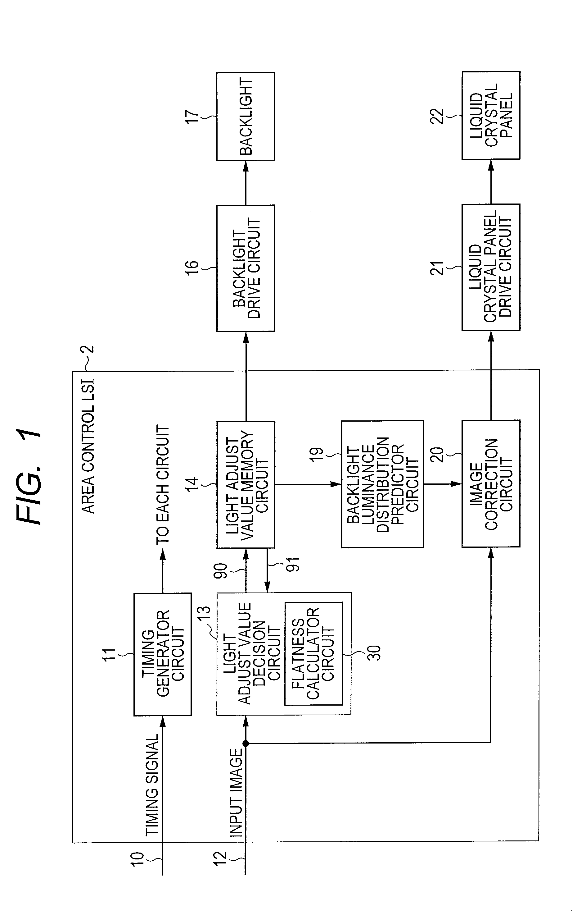
[0052]The first embodiment of this invention is described while referring to FIG. 1. A liquid crystal panel 22 in the figure is equivalent to the image display device, and a backlight 17 is equivalent to the light source unit. The backlight 17 contains a plurality of light sources whose light emission intensity can be separately controlled according to each of the plural subdivided screen areas. The backlight 17 is mounted so that the light generated by these light sources becomes light transmitting through the liquid crystal panel 22.

[0053]The reference numeral 12 in the figure denotes the input image for the display, reference numeral 10 denotes a signal indicating timing information for the input image 12, and is equivalent to dot clock and synchronous signal. The timing generator circuit 11 generates different types of timing signals such as clocks, addresses, and trigger signals, and supplies these timing signals to other circuits. A description of these timing signals is omitt...

second embodiment

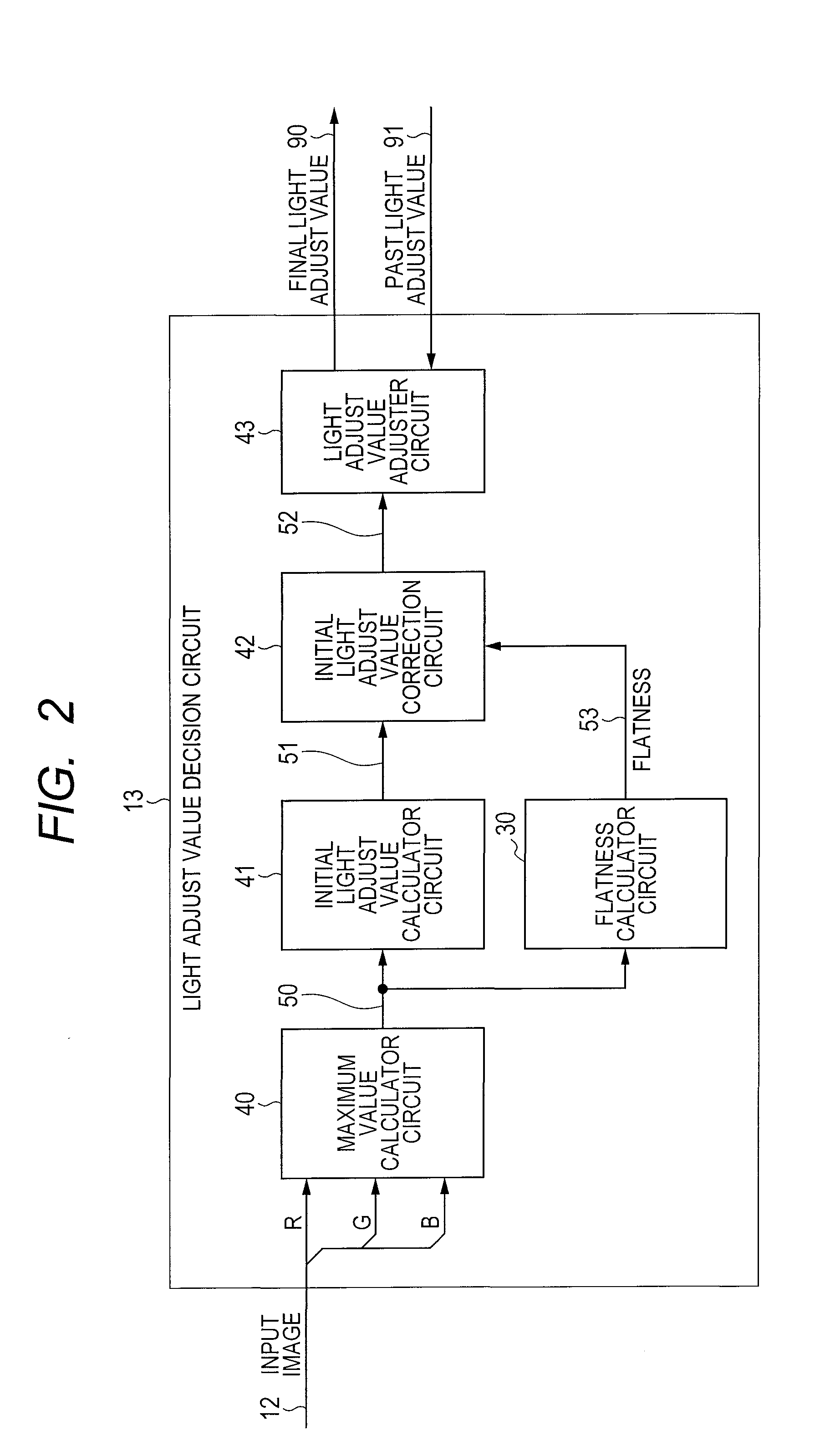
[0077]In the first embodiment, a binary H, L signal was employed as the flatness signal 53. More detailed control can however be achieved by employing a multi-value signal. An embodiment employing multi-value signals is described next. The concentration decision unit 32 in FIG. 3 utilized 1 as a threshold value but three other different threshold values are prepared, and by setting the output from concentration decision unit 32 to show which threshold the concentration in each area has exceeded, the concentration decision unit 32 can provide 4 types of outputs. Here, the three threshold values are threshold A, threshold B, and threshold C in order starting from the smallest value. Output values from the concentration decision unit 32 are defined such that: a concentration smaller than threshold A is 0, a concentration larger than threshold A and also smaller than threshold B is 1, a concentration larger than threshold B and also smaller than threshold C is 2, and a concentration lar...

third embodiment

[0081]If only the color tone of the pixels in the area were changed in the structures of the first and second embodiments then that area might be mistakenly recognized as a flat area. In an image for example where the pixels include the three RGB components, if the maximum values of these three components are within a fixed range within the area then that area will be recognized as a flat area even if there is a large fluctuation width among the RGB components.

[0082]One method to prevent this faulty recognition is to calculate the flatness in each RGB component and utilize those values to calculate the flatness of each area. This method is illustrated in FIG. 8. In this structure, the flatness calculator circuits 30a, 30b, 30c are provided in a format corresponding to each of the RGB components. These circuit structures are the same as the flatness calculator circuit 30 in the first embodiment. A flatness synthesizer circuit 44 calculates the total flatness of the area from the flat...


PUM


Abstract

An image display device using the area control method for eliminating irregularities as seen from the side and also capable of lowering power consumption. The degree of flatness indicating the image flatness of an image in each image area is calculated, and in areas that are flat the light source luminance is set high in order to lessen irregularities as seen from the side; and in areas that are not flat the irregularities are difficult to perceive as seen from the side so an effect that cuts power consumption is obtained without having to correct the light source luminance.

Description

CLAIM OF PRIORITY[0001]The present application claims priority from Japanese patent application JP 2009-294509 filed on Dec. 25, 2009, the content of which is hereby incorporated by reference into this application.FIELD OF THE INVENTION[0002]The present invention relates to an image display device for displaying image data that was input and relates in particular to an image display device capable of lowering power consumption.BACKGROUND OF THE INVENTION[0003]In display devices such as LCD that utilize backlighting without emitting their own light, the backlighting usually consumes most of the electrical power. In such cases, lowering the power consumed by backlighting is the key to lowering the total power consumption in the display device.[0004]Attempts were therefore made to lower power consumption in the display device by lowering the light intensity of the backlight in dark image scenes. Simply lowering the light intensity of the backlight to 1 / N also lowers the screen brightne...

Claims


Application Information

Patent Timeline
Patent Type & Authority Patents(United States)
IPC IPC(8): G09G3/34
CPCG09G3/3426G09G2320/0276G09G2320/028G09G2320/0646G09G2320/0653G09G2320/068G09G2330/021G09G2354/00G09G2360/16
Inventor TANAKA, KAZUHIKOTSURU, YASUTAKAOGI, YUYA
Owner MAXELL HLDG LTD
Learn More