
Use of a transponder for servicing work on an installation component

a technology for installing components and transponders, which is applied in the direction of instruments, subscriber stations, indirect connection, etc., can solve the problems of inability to read by the human eye, disconnection of components, and difficult tasks and potentially susceptible to errors, so as to increase occupational safety

Inactive Publication Date: 2013-05-28
STEAG ENERGY SERVICES
View PDF18 Cites 0 Cited by
  • Summary
  • Abstract
  • Description
  • Claims
  • Application Information

AI Technical Summary

Benefits of technology

[0009]The present invention relates to providing a solution which allows the aforementioned drawbacks and risks to be avoided and an increase in occupational safety in a commercial installation, particularly a power plant, to be achieved.

Problems solved by technology

Information stored on the transponder is stored invisibly to humans, however, and therefore cannot be read by the human eye.
This task is difficult and potentially susceptible to error, since each disconnection step needs to be checked against each disconnection step in all other active disconnection plans.
Although the use of a computer-aided method of conflict recognition as addressed above increases the reliability of the check significantly, computer-aided disconnection does not stretch to the actual location of the disconnection, which means that human error can result in the disconnection of a component despite precise guidelines.
Furthermore, it is possible for the disconnection to be reversed for an incorrect component because an annotation or marker indicating the disconnection is not present on the component, is illegible or is inaccurate.
Another source of error which can result in the disconnection of a component being reversed is harboured by paper-based evaluation of a disconnection plan as a result of the overlooking of still active disconnection states, so that an individual component is incorrectly normalized, i.e. connected or switched on.
Another risk of unwanted reversal of the disconnection results from a marker which has been attached to the component or to a switching point for this component in this regard having fallen off or being unrecognizable or having been inadvertently removed.

Method used


Image

  • Use of a transponder for servicing work on an installation component
  • Use of a transponder for servicing work on an installation component
  • Use of a transponder for servicing work on an installation component

Examples


Embodiment Construction

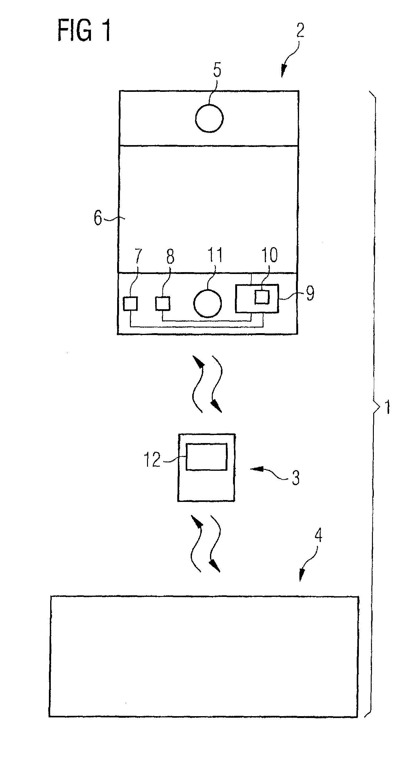
[0055]FIG. 1 schematically shows an information system, denoted overall by reference numeral 1, which comprises a transponder 2, a mobile read / write unit 3 and an EDP system 4. The proportions shown in the illustration between the transponder 2, the mobile read / write unit 3 and the EDP system 4 do not necessarily correspond to the actual relationships.

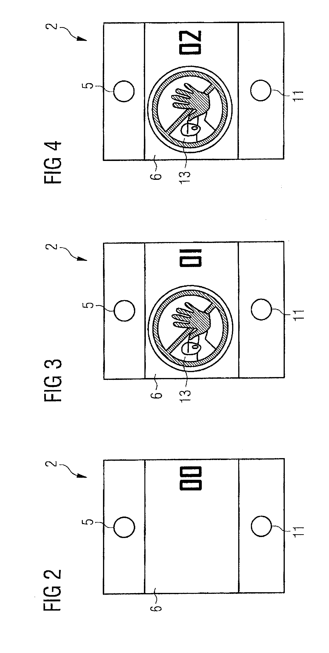
[0056]The transponder 2 has an opening 5 which is in the form of a hole and through which it is possible to put a mounting element in order to allow the transponder 2 to be permanently fitted to a component of a commercial installation. Besides mechanical mounting options provided by the opening 5, the transponder 2 can also have a lateral face, which is remote from a visual display unit 6 of the transponder 2, fitted on and / or to the component of the installation by means of an adhesive or the like. In particular, the transponder is intended to be used in connection with a commercial power plant.

[0057]The transponder 2, which is in th...


PUM


Abstract

Described is the use of a transponder in a commercial installation, particularly a power plant, which allows problems and dangerous situations existing in this context to be avoided and the attainable occupational safety in a commercial installation, particularly a power plant, to be increased. The transponder includes a reception element, a transmission element, a visual display unit and a memory element and also a control element which is operatively connected to these, in a commercial installation, particularly a power plant, in an arrangement or positioning on or in proximity to a component or at a switching or measuring point associated with the component for the purpose of visually displaying an operating state for the component or the switching or measuring point associated therewith using the visual display unit of the transponder.

Description

PRIORITY CLAIM[0001]This application claims the benefit of the filing date of EP Application Serial No. 08 166 450 filed on Oct. 13, 2008, the disclosure of this application is hereby incorporated herein by reference.FIELD OF INVENTION[0002]The present invention relates to the use of a transponder in a commercial installation, particularly a power plant. In addition, the present invention relates to a method for performing maintenance, servicing and / or repair work on a component and / or on a switching or measuring point associated with said component in a commercial installation, particularly a power plant. Furthermore, the present invention relates to a commercial installation, particularly a power plant, which is equipped with a transponder that is used therein.BACKGROUND INFORMATION[0003]Transponders are radio communication appliances which are increasingly often used for identifying a wide variety of objects. In comparison with conventional bar code patterns, which are likewise u...

Claims


Application Information

Patent Timeline
Patent Type & Authority Patents(United States)
IPC IPC(8): H04Q5/22G21C7/36G21C17/00
CPCG06K19/07703G06K19/07749
Inventor OFFERMANN, WOLFGANGSTEPHAN, MARTIN
Owner STEAG ENERGY SERVICES
Learn More