
Thermal compression therapy apparatus and system

a technology of thermal compression therapy and apparatus, which is applied in the field of medical devices and therapy systems, can solve the problems of the high cost of the core portion of the thermal compression therapy apparatus

Inactive Publication Date: 2013-05-21
MALDONADO MEDICAL
View PDF27 Cites 34 Cited by
  • Summary
  • Abstract
  • Description
  • Claims
  • Application Information

AI Technical Summary

Benefits of technology

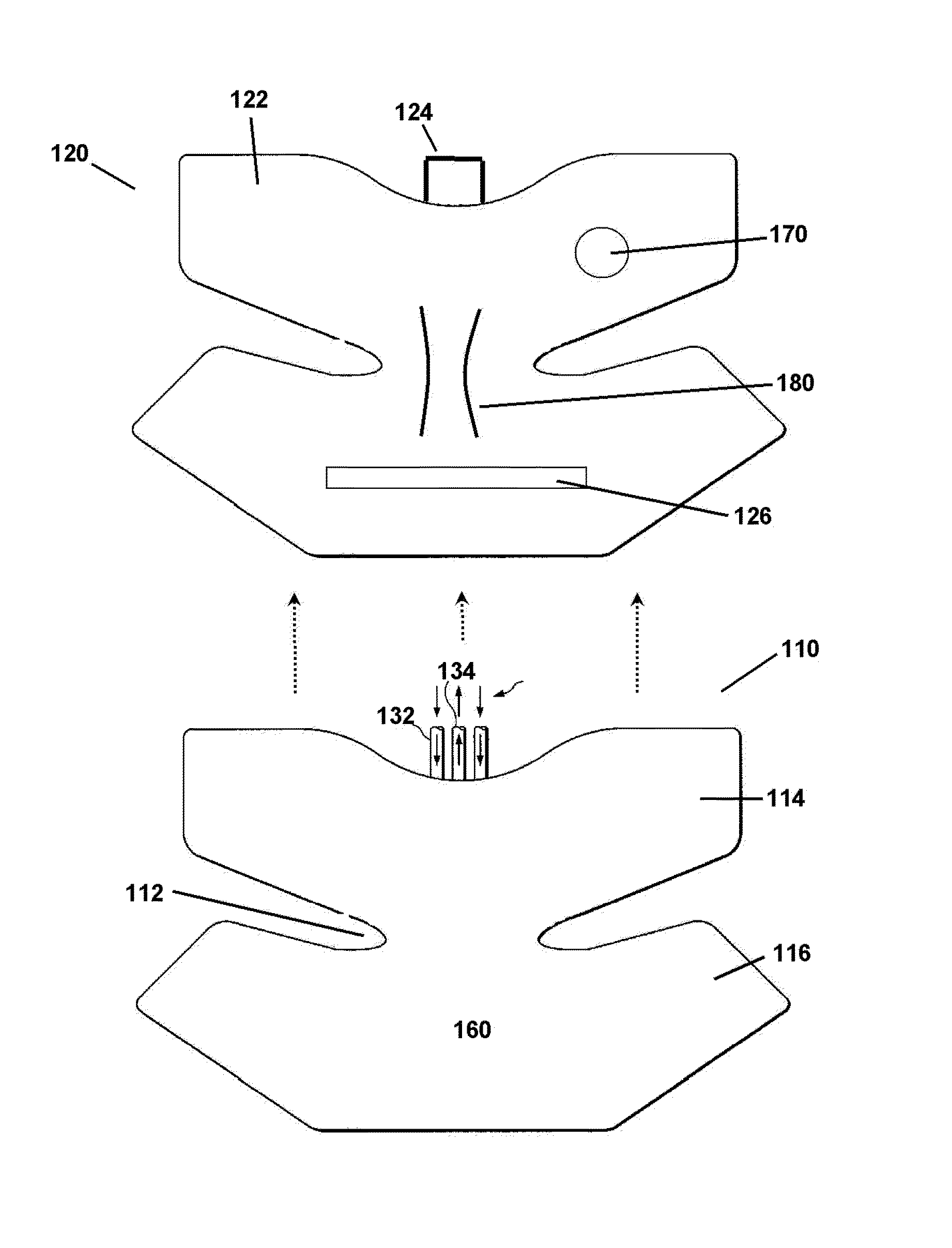
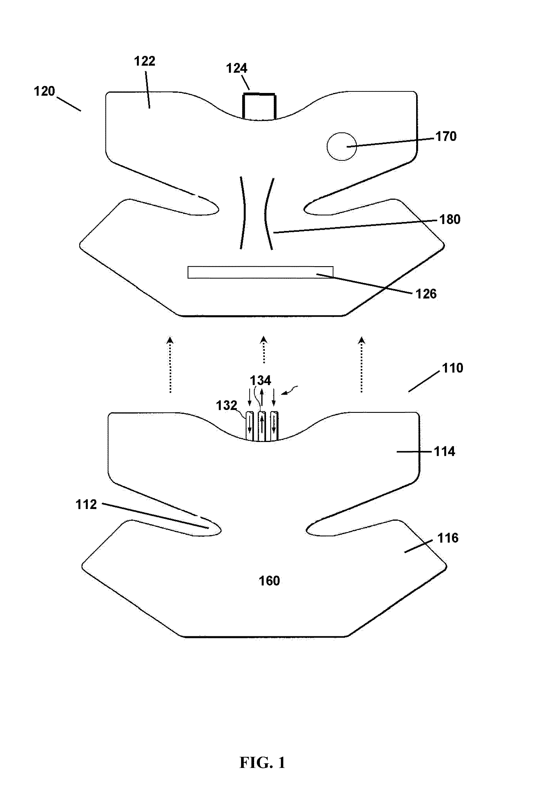
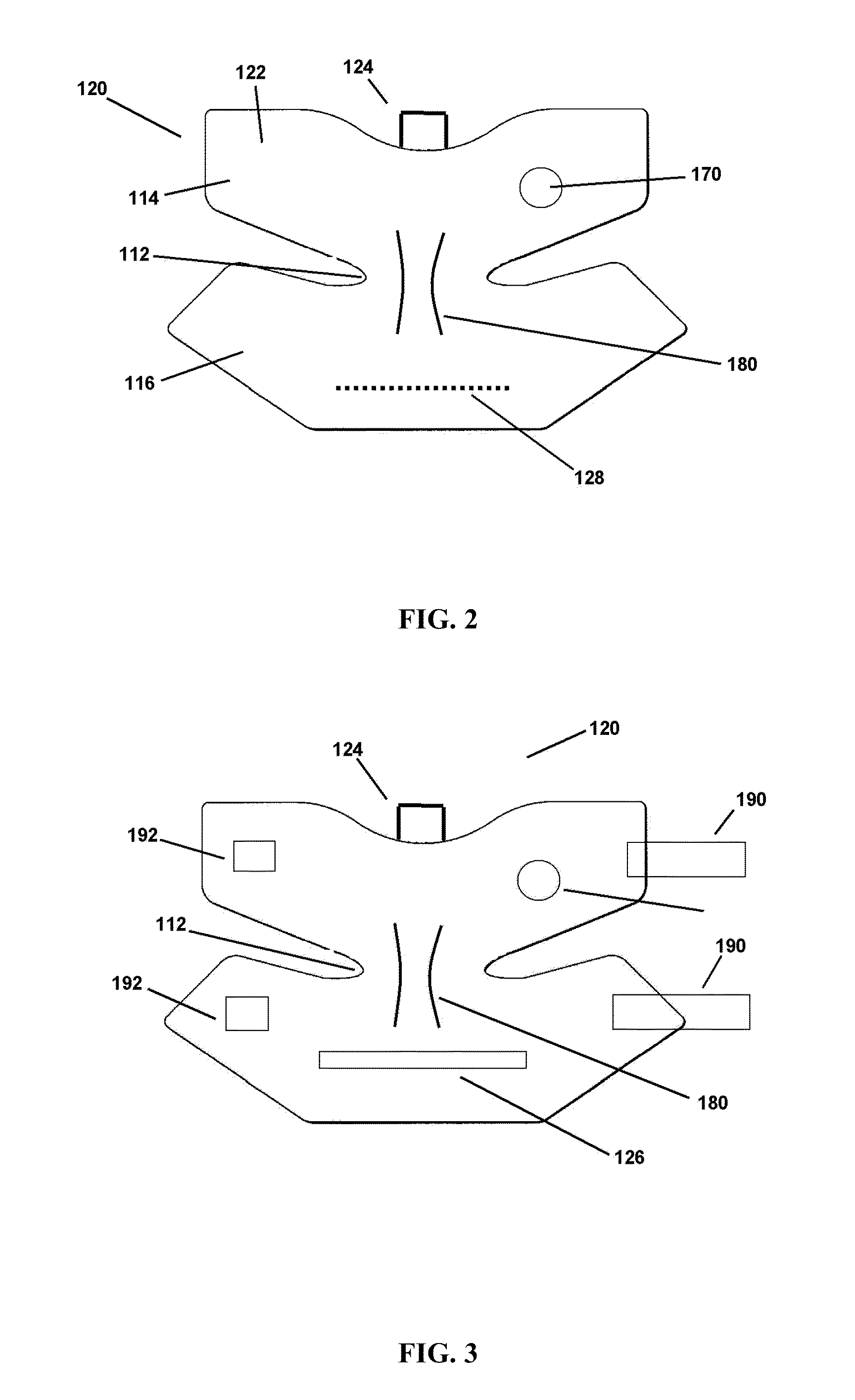
The patent describes an apparatus and system for compression and thermal therapy that can be used with multiple patients. The system includes a reusable core with separate compression, heating, and cooling components, and a disposable outer cover that comes into contact with the patient's body. The outer cover has a temperature nodule for monitoring the patient's skin. The system can also have an improved therapeutic combination of compression, cold, and heat therapy, with a cover that defines an interior volume and an exterior region. The cover has a hook and loop attachment means for easy positioning of the core. Overall, the system provides efficient and effective therapy for a wide range of patients.

Problems solved by technology

Nevertheless, the systems and methods described in the prior art continue to suffer from various shortcomings and are in need of improvement.
One such shortcoming relates to the high cost associated with the core portion of the thermal compression therapy apparatus.
The core portion, that portion of the apparatus that is wrapped around an area of the patient's body (a knee joint for example) is generally an expensive item.
Thus, the core can easily become contaminated with blood and other discharges and fluids emitted by the recovering patient.
However, given the somewhat delicate nature of the materials and structures contained within the core a sterilization process is not effective.
Given the cost of the core, throwing each core away after a single use is an expensive option.
Further, the core structure itself suffers from various limitations in the present design and is in need of improvement.
During such therapies there is a tendency within the core to fold and obstruct portions of the core that is repeatedly being bent.
The cores can then suffer from malfunction or poor performance (even distribution of fluids) as various tubings are obstructed.
In current methods there is no direct way to determine the skin temperature of the patient in that area where the patient is receiving therapy.

Method used


Image

  • Thermal compression therapy apparatus and system
  • Thermal compression therapy apparatus and system
  • Thermal compression therapy apparatus and system

Examples


Embodiment Construction

[0026]The present invention can be understood more readily by reference to the following detailed description, examples, drawing, and claims, and their previous and following description. However, before the present devices, systems, and / or methods are disclosed and described, it is to be understood that this invention is not limited to the specific devices, systems, and / or methods disclosed unless otherwise specified, as such can, of course, vary. It is also to be understood that the terminology used herein is for the purpose of describing particular aspects only and is not intended to be limiting.

[0027]The following description of the invention is provided as an enabling teaching of the invention in its best, currently known aspect. To this end, those skilled in the relevant art will recognize and appreciate that many changes can be made to the various aspects of the invention described herein, while still obtaining the beneficial results of the present invention. It will also be ...


PUM


Abstract

A combined heating, cooling, and compression therapy system is provided. The system is configured for automated use with a controller. The system can have a core with separate channels for providing cold and heat and compression therapy; a cover for receiving the core; and a skin sensitive temperature node attached to the core cover.

Description

CONTINUITY DATA[0001]This application claims priority to and the benefit of U.S. Provisional Application Ser. No. 61 / 134,677, filed on Jul. 10, 2008, and U.S. Provisional Application Ser. No. 61 / 134,676, filed on Jul. 10, 2008, both of which are incorporated herein in their entirety.FIELD OF THE INVENTION[0002]A medical device and therapy system is presented. More particularly, an apparatus and system for providing combined heating or cooling and compression therapy is presented for use, by way of general example, in reducing edema and pain and preventing deep vein thrombosis (DVT).BACKGROUND OF THE INVENTION[0003]Various medical devices have been developed to deliver warming therapy and cooling therapy to patients recovering from injuries or surgeries. Additionally, it is known to provide a pressurized massage therapy, sometimes referred to as external pneumatic compression (“EPC”), to these patients. Typical recipients of these therapies are patients recovering from orthopedic sur...

Claims


Application Information

Patent Timeline
IPC IPC(8): A61H7/00
CPCA61H9/00A61H1/00A61H9/0092A61F7/00A61H2230/505A61H2201/0207A61H2201/0242A61H2201/1654A61H2201/1688A61H2201/5005A61H2201/5015A61H2201/5035A61H2201/5043A61H2205/102A61H2205/12A61H2209/00
Inventor MAXON-MALDONADO, GREGORY BRIANCALLINAN, ADAM M.
Owner MALDONADO MEDICAL
Learn More