
Vehicle driving assist system

a technology of vehicle driving and assist system, which is applied in the field of vehicle driving assist system, can solve the problems of difficulty in driving operations in accordance with the driver's or her own instructions

Inactive Publication Date: 2013-05-14
NISSAN MOTOR CO LTD
View PDF26 Cites 17 Cited by
  • Summary
  • Abstract
  • Description
  • Claims
  • Application Information

AI Technical Summary

Benefits of technology

The present invention provides a driving assist system for a vehicle that can detect preceding objects and calculate the risk potential of the vehicle and the obstacle approaching it. The system includes two driving assistance control systems: one controls the driver's reaction force and the other controls the vehicle's braking force to maintain a safe distance from the obstacle. The system also includes a transition detecting section to detect any changes in the operating state of the two control systems, and a control adjusting section to adjust the control executed by the two systems when a change in operating state is detected. This system helps the driver to execute driving operations in accordance with their intent and ensures safe driving.

Problems solved by technology

With the conventional driving assist systems just described, it is difficult for the driver to execute driving operations in accordance with his or her intent when the system is switching between an automatic cruise control or a following distance control and accelerator reaction force control.

Method used


Image

  • Vehicle driving assist system
  • Vehicle driving assist system
  • Vehicle driving assist system

Examples


first embodiment

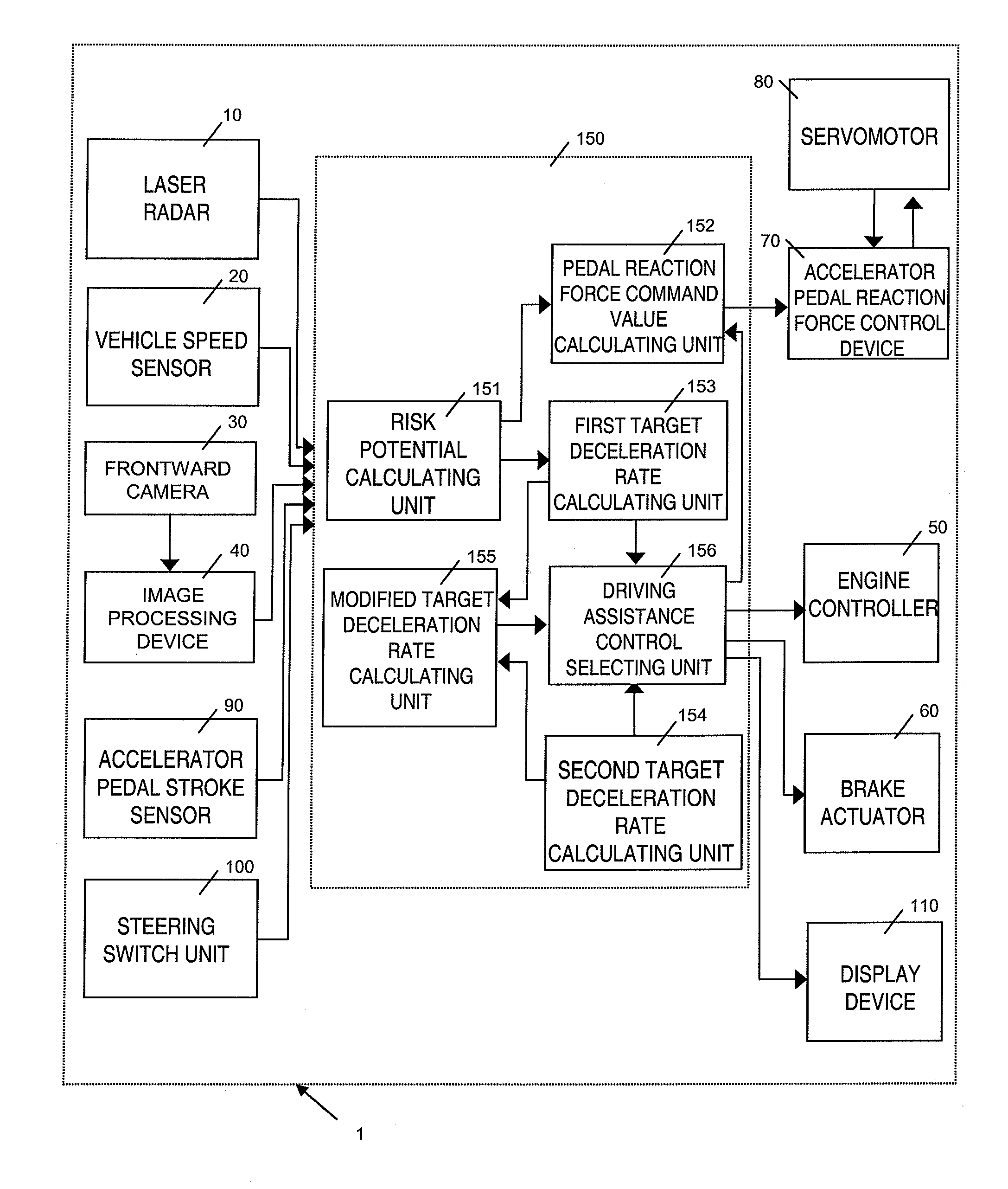
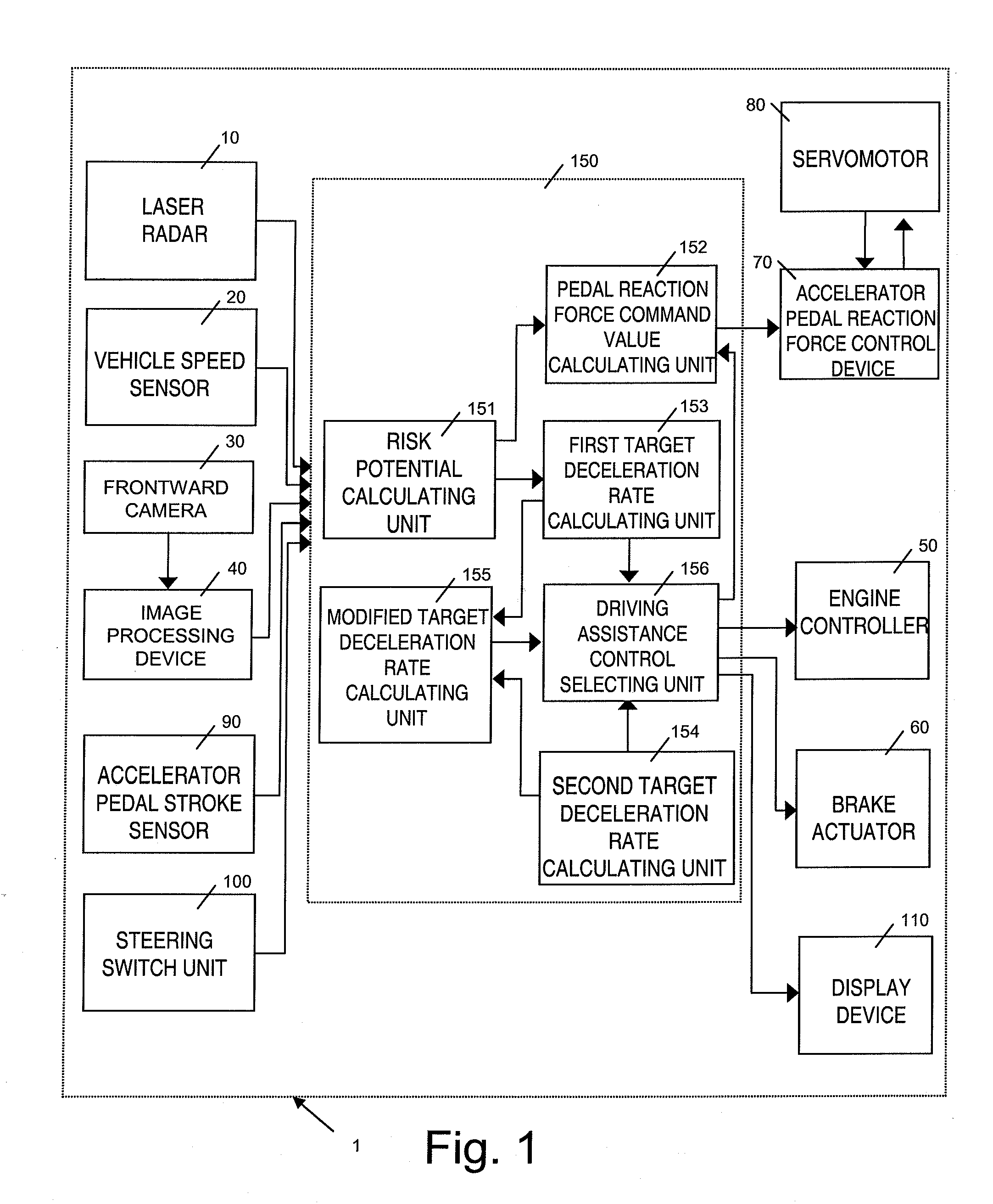
[0065]The operation of a vehicle driving assist system 1 in accordance with the first embodiment will now be explained. First, an overview of the operation will be provided.

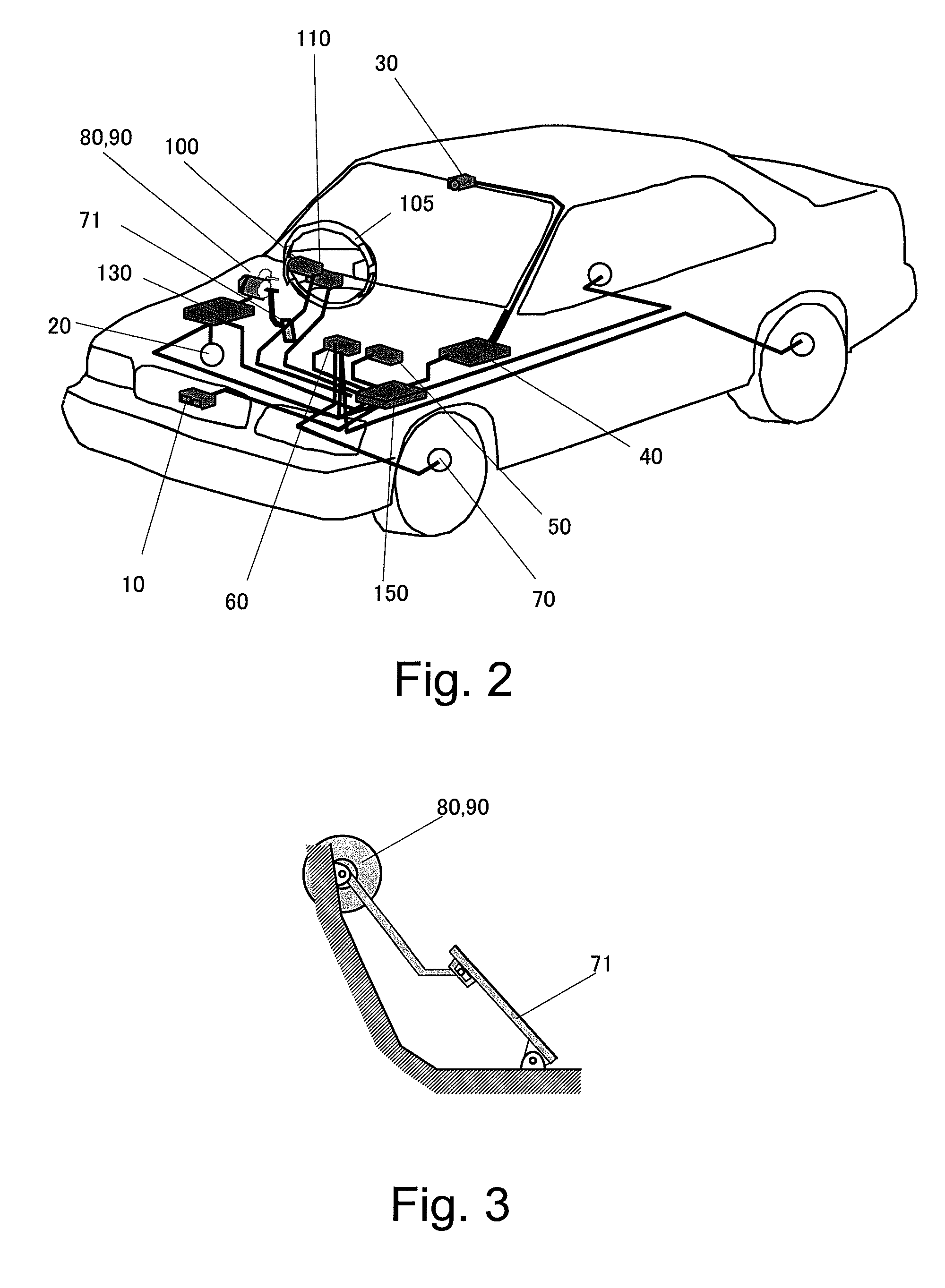
[0066]The controller 150 calculates the risk potential RP of the host vehicle with respect to an obstacle in the vicinity of the host vehicle based on the running condition of the host vehicle and the traveling environment (traveling situation) surrounding the host vehicle detected by the laser radar 10, the vehicle speed sensor 20, and the frontward camera 30. The term “risk potential RP” refers to the degree of risk or possibility of danger. In this embodiment, the risk potential is contrived to increase as the host vehicle and an obstacle existing in the vicinity of the host vehicle approaches each other. Thus, it can be the that the risk potential is a physical quantity that expresses how close the host vehicle and the obstacle are to each other, i.e., the degree to which the host vehicle and the obstacle hav...

second embodiment

[0123

[0124]A vehicle driving assist system in accordance with a second embodiment of the present invention will now be explained. The basic constituent features of a vehicle driving assist system 1 in accordance with the second embodiment are the same as those of the first embodiment shown in FIGS. 1 and 2. The second embodiment will be explained chiefly by describing its differences with respect to the first embodiment.

[0125]In the second embodiment, when the braking / driving force is modified while the following distance control is overridden, the driver's requested driving force drv_trq is modified in a manner that takes into account the accelerator pedal depression rate Apv during the override state.

[0126]The operation of a vehicle driving assist system 1 in accordance with the second embodiment will now be explained in detail with reference to FIGS. 14 and 15. FIGS. 14 and 15 are flowcharts showing the processing steps of a driving assistance control program executed by the cont...

third embodiment

[0134

[0135]A vehicle driving assist system in accordance with a third embodiment of the present invention will now be explained. The basic constituent features of a vehicle driving assist system 1 in accordance with the third embodiment are the same as those of the first embodiment shown in FIGS. 1 and 2. The third embodiment will be explained chiefly by describing its differences with respect to the first embodiment.

[0136]In the third embodiment, the prescribed amount of time T for which the braking / driving force modification control is continued during the override state (state in which following distance control is overridden) is modified based on the difference Δrf between the repulsive torque rf1 of the RP conveyance control and the repulsive torque rf2o of the following distance control at the time when overriding of the following distance control started. The difference Δrf equals rf1 minus rf2o (Δrf=rf1−rf2o).

[0137]FIG. 17 shows a graph plotting a modification control contin...


PUM


Abstract

A vehicle driving assist system is provided that calculates a risk potential indicative of a degree of convergence between the host vehicle and the preceding obstacle. A first driving assistance control system controls at least one of an actuation reaction force exerted by a driver-operated driving operation device and a braking / driving force exerted against the host vehicle based on the risk potential calculated. A second driving assistance control system controls the braking / driving force of the host vehicle such that a headway distance is maintained between the host vehicle and the obstacle. A transition detecting section detects a transition of operating states of the first and second driving assistance control systems. The control adjusting section adjusts the control executed by the first and second driving assistance control systems when a transition of operating state is detected.

Description

CROSS-REFERENCE TO RELATED APPLICATIONS[0001]This application claims priority to Japanese Patent Application No. 2006-142713 filed 23 May 2006. The entire disclosure of Japanese Patent Application No. 2006-142713 is hereby incorporated herein by reference.BACKGROUND OF THE INVENTION[0002]1. Field of the Invention[0003]The present invention generally relates to a vehicle driving assist system configured to assist a driver with respect to the operation of a vehicle.[0004]2. Background Information[0005]Various vehicle driving assist systems has been proposed to assist a driver with respect to the operation of a vehicle. An example of a vehicle assist system is disclosed in Japanese Laid-Open Patent Application No. 2000-54860. In this publication, the vehicle driving assist system increases an accelerator pedal reaction force such that the driver can rest his or her foot on the accelerator pedal during automatic cruise control. With such a system, the driver can override the automatic c...

Claims


Application Information

Patent Timeline
Patent Type & Authority Patents(United States)
IPC IPC(8): G08G1/16B60K26/02B60K28/14B60K31/00B60R21/00B60T7/12B60W10/04B60W10/06B60W10/18B60W10/184B60W30/00B60W30/09B60W30/095B60W30/16B60W50/035F02D29/02
CPCB60W10/06B60W10/184B60W30/16B60W50/16B60K31/0008B60K26/021
Inventor KUGE, NOBUYUKIKONDOH, TAKAYUKIONOZUKA, AKIRAYAMAMURA, TOMOHIROKAMISUKI, YOSHIHARU
Owner NISSAN MOTOR CO LTD
Learn More