
Suspended cab rollover protection system (ROPS) attachment for a 4WD agricultural tractor

a technology for agricultural tractor and rollover protection system, which is applied in the direction of roofs, pedestrian/occupant safety arrangements, vehicular safety arrangements, etc., can solve the problems of insufficient arrangement, heavy-duty tractors may not provide adequate ride comfort for operators, and machineries place considerable demands on the construction of cab suspensions

Active Publication Date: 2013-04-30
CNH IND AMERICA LLC
View PDF20 Cites 13 Cited by
  • Summary
  • Abstract
  • Description
  • Claims
  • Application Information

AI Technical Summary

Benefits of technology

[0005]Accordingly, the present invention, in any of the embodiments described herein, may provide one or more of the following advantages:
[0009]It is a further object of the present invention to provide a cab suspension device for an agricultural tractor cab that incorporates resilient bumpers to minimize metal-to-metal contact within the device during normal operations.
[0010]It is a still further object of the present invention to provide a cab suspension device for an agricultural tractor that is sufficiently robust to withstand expected tractor roll over loads without loss of structural integrity.
[0011]It is a still further object of the present invention to provide a suspended cab mounting device for an agricultural tractor having a separate cab suspension apparatus wherein the mounting device will withstand tractor roll over loads without loss of structural integrity.
[0012]It is a still further object of the present invention to provide a cab suspension device for a ROPS-equipped agricultural tractor that is durable in construction, inexpensive of manufacture, carefree of maintenance, easily assembled, and simple and effective to use.
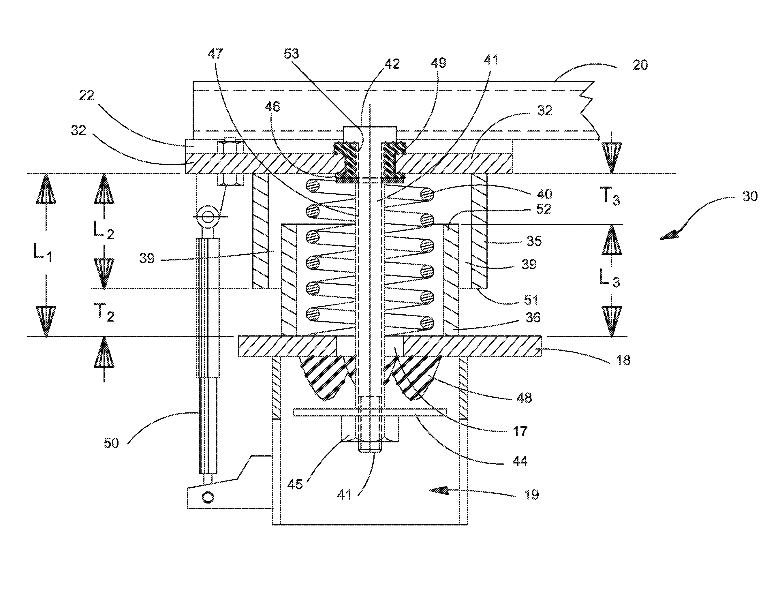
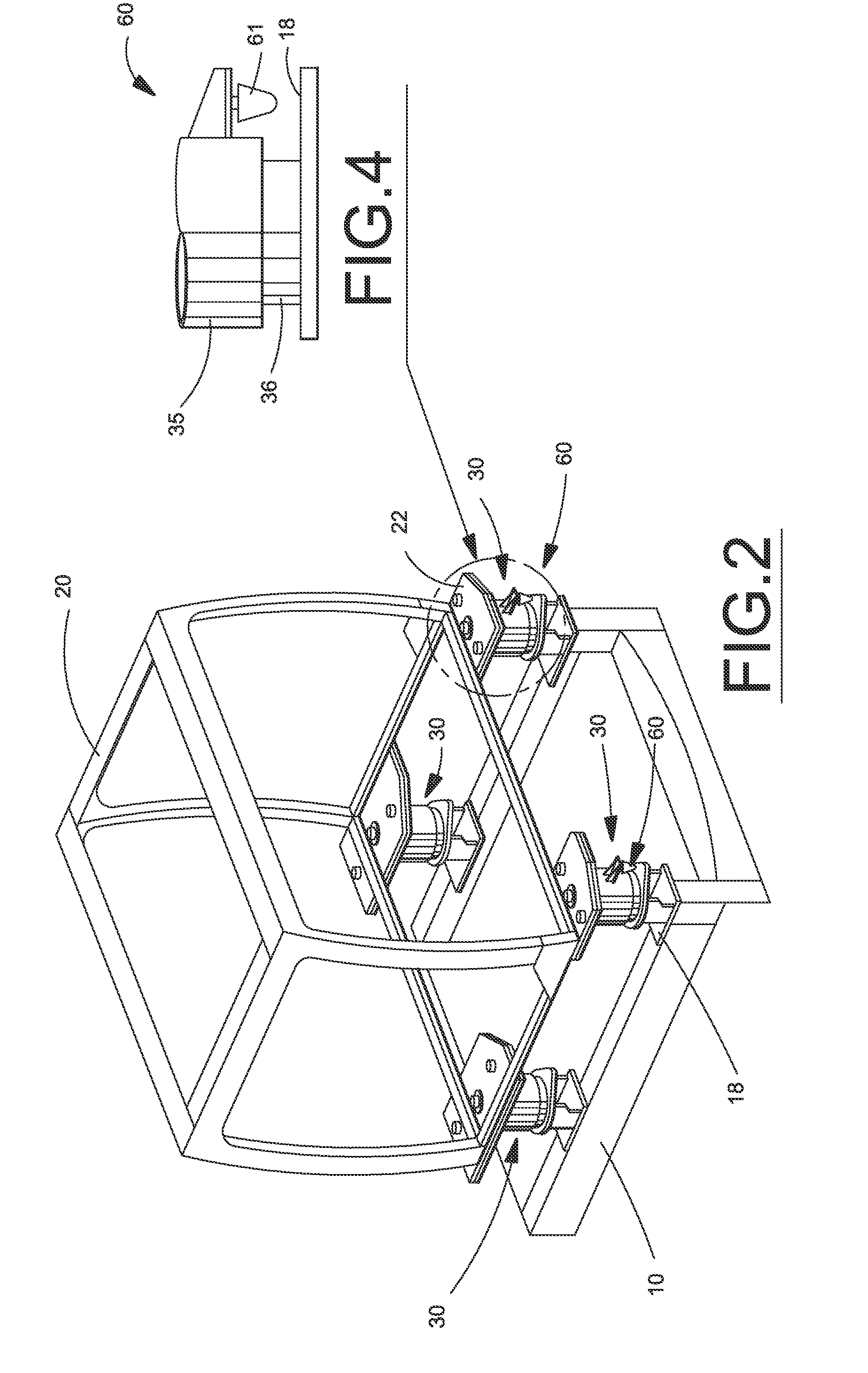
[0013]These and other objects are achieved by providing a cab suspension device for an agricultural tractor comprising a pair of concentrically aligned tubes co-axially arranged around a conventional cab suspension spring apparatus. One of the pair of tubes is connected to the tractor frame while the second is attached to the cab frame. The lengths of the tubes are shorter than the static length of the spring apparatus to allow limited telescoping movement of the tubes during dynamic compression of the spring apparatus without causing contact between the tube ends and the opposing frames. The dynamic extension during telescoping movement of the spring apparatus is controlled by a spring retainer. An annular space between the tubes allows for limited lateral displacement of the spring apparatus without causing contact between the tubes. The limits are configured to permit normal operational movement of the spring apparatus without contact of the tubes. During vehicle roll over events, the normal operational loads of the spring apparatus are exceeded and the tubes will come in contact with one another and / or the opposing frame. The tubes and the spring retainer provide a rigid load transfer path for RAPS loads from the cab to the vehicle frame.

Problems solved by technology

Construction and agricultural machinery places considerable demands on the operator's cab suspension construction.
This arrangement has been found to be insufficient for heavier duty 4WD agricultural tractors which require moveable connections at the four corners of the cab mounting structure to provide adequate operator comfort.
As this attachment is relatively rigid, adequate operator ride comfort may not be provided on heavy duty tractors.

Method used


Image

  • Suspended cab rollover protection system (ROPS) attachment for a 4WD agricultural tractor
  • Suspended cab rollover protection system (ROPS) attachment for a 4WD agricultural tractor
  • Suspended cab rollover protection system (ROPS) attachment for a 4WD agricultural tractor

Examples


Embodiment Construction

)

[0019]Many of the fastening, connection, processes and other means and components utilized in this invention are widely known and used in the field of the invention described, and their exact nature or type is not necessary for an understanding and use of the invention by a person skilled in the art, and they will not therefore be discussed in significant detail. Also, any reference herein to the terms “forward” or “rearward,”“left” or “right,”“up” or “down,” or “top” or “bottom” are used as a matter of mere convenience, and are determined by standing at the rear of the machine facing in its normal direction of travel. Furthermore, the various components shown or described herein for any specific application of this invention can be varied or altered as anticipated by this invention and the practice of a specific application of any element may already be widely known or used in the art by persons skilled in the art and each will likewise not therefore be discussed in significant de...


PUM


Abstract

A cab suspension device for an agricultural tractor comprising a pair of concentrically aligned tubes co-axially arranged around a conventional cab suspension spring apparatus. One of the pair of tubes is connected to the tractor frame while the second is attached to the cab frame. The lengths of the tubes are shorter than the static length of the spring apparatus to allow limited telescoping movement of the tubes during dynamic compression of the spring apparatus without causing contact between the tube ends and the opposing tractor and cab frames. The dynamic extension during telescoping movement of the spring apparatus is controlled by a spring retainer. An annular space between the tubes allows for limited lateral displacement of the spring apparatus without causing contact between the tubes. The limits are configured to permit normal operational movement of the spring apparatus without contact of the tubes. During vehicle roll over events, the normal operational loads of the spring apparatus are exceeded and the tubes will come in contact with one another and / or the opposing frame. The tubes and the spring retainer provide a rigid load transfer path for ROPS loads from the cab to the vehicle frame.

Description

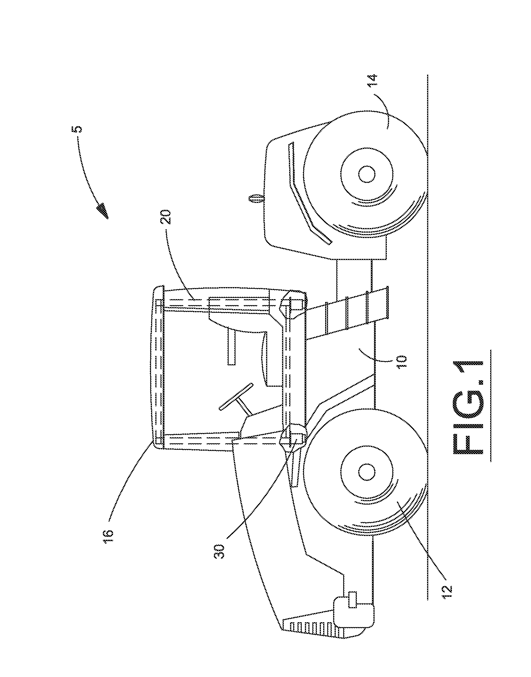
BACKGROUND OF THE INVENTION[0001]The present invention relates to a device for suspending a cab on a work vehicle and, more particularly, to a cab suspension device that is also capable of transferring loads from the rollover protection systems (ROPS) to the vehicle chassis when required.[0002]Construction and agricultural machinery places considerable demands on the operator's cab suspension construction. In order to make the working environment of the driver comfortable, the suspension must be capable of reducing / eliminating the relatively powerful vibrations and shocks which are otherwise transmitted from the vehicle frame to the cab. Moreover, for reasons of safety, the suspension must be sufficiently strong to retain the cab on the frame even if the vehicle should overturn. Typical lighter duty agricultural tractor cab suspensions are designed with pivot connections at the front of the cab and vertical sprung connections at the rear of the cab. This arrangement has been found t...

Claims


Application Information

Patent Timeline
Patent Type & Authority Patents(United States)
IPC IPC(8): B60R21/13B62D33/06B62D27/04
CPCB60R21/131B62D33/0604B62D33/0617
Inventor RASSET, JOHN T.BAUTZ, CHAD A.ZURN, DANIEL J.
Owner CNH IND AMERICA LLC
Learn More