
Positive airway pressure apparatus

a pressure apparatus and positive technology, applied in the field of positive airway pressure apparatus, can solve the problem of inconvenient adjustmen

Active Publication Date: 2013-04-23
GALEMED
View PDF7 Cites 6 Cited by
  • Summary
  • Abstract
  • Description
  • Claims
  • Application Information

AI Technical Summary

Benefits of technology

The apparatus described in this patent is designed to provide positive airway pressure in a respiratory circuit. It includes a container for holding liquid and a drop tube assembly consisting of a gas tube and a drop tube. The gas tube is connected to the expiratory tubing of the respiratory circuit and the drop tube is movable up and down in response to the rotational movement of the gas tube. The drop tube can be positioned at various locations below the liquid level and its specific design allows for easy adjustment of its position. The technical effects of this apparatus are improved patient respiratory support and the ability to manage airway pressure in a more effective way during respiratory therapy.

Problems solved by technology

Although the design of the aforesaid disclosed apparatus is intended to ensure the secure positioning of the drop tube in the liquid at the desired depth, it does so at the expense of requiring various lengths of the elongated drop tube to extend upwardly out from the lid of the apparatus and is inconvenient to adjust.

Method used


Image

  • Positive airway pressure apparatus
  • Positive airway pressure apparatus
  • Positive airway pressure apparatus

Examples


Embodiment Construction

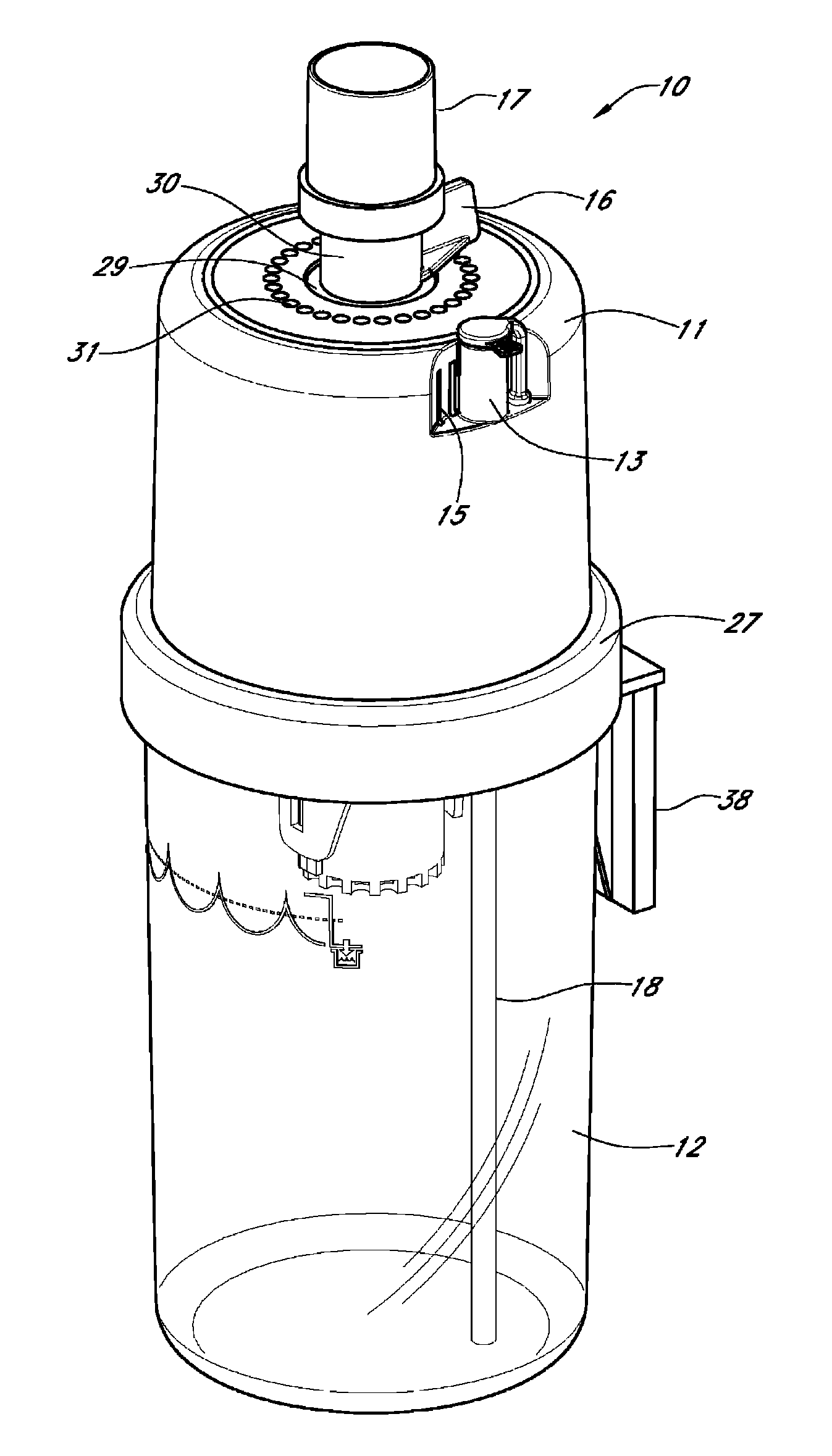
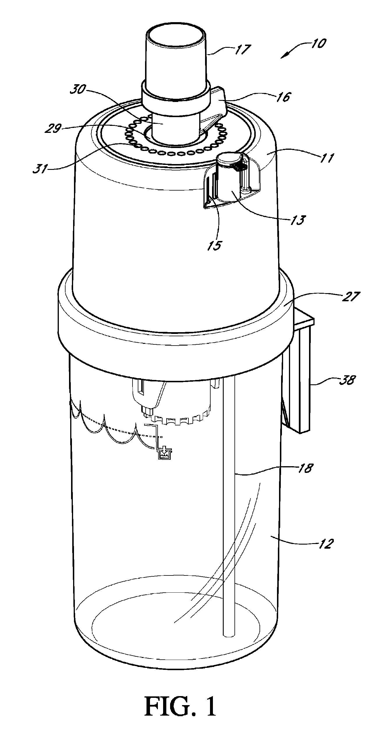
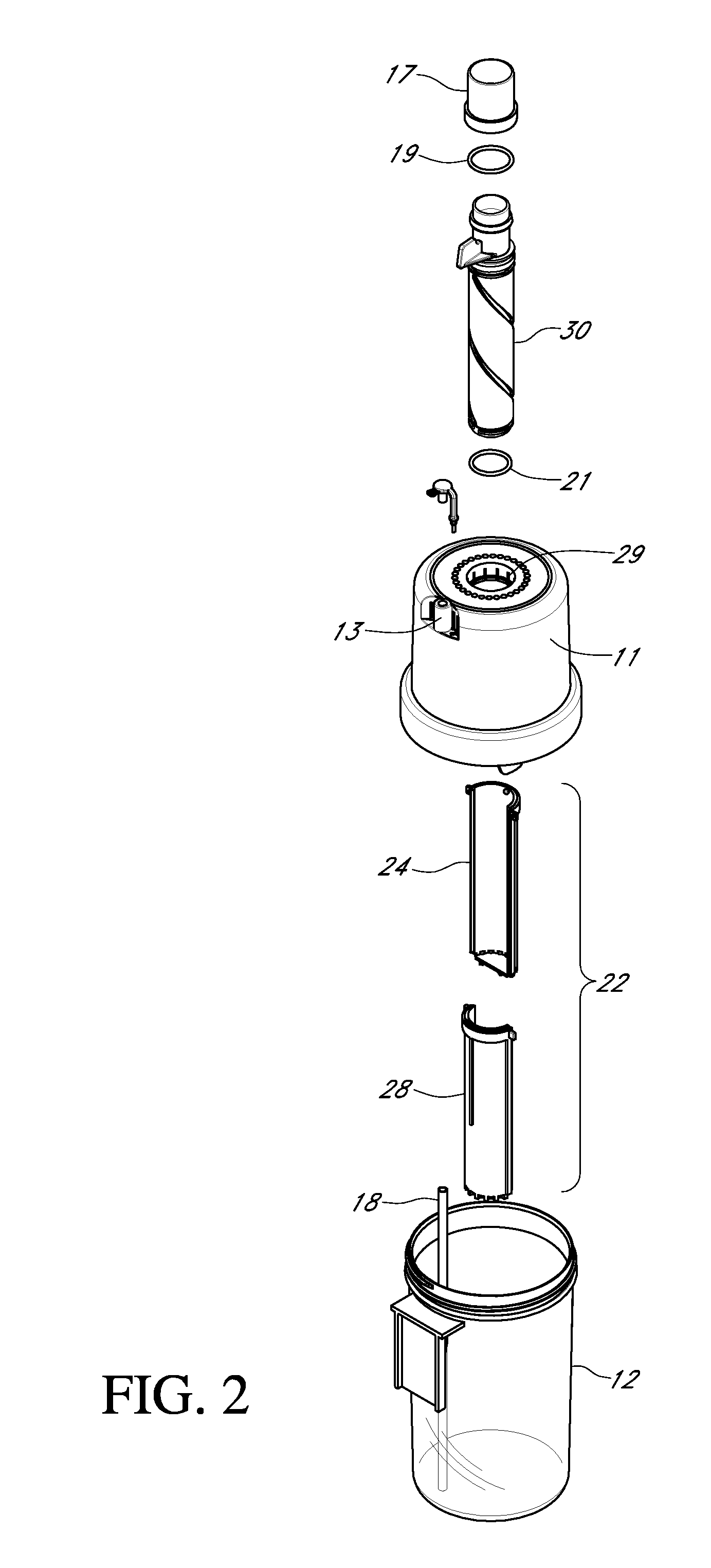
[0015]The exterior components and features of the assembled apparatus 10 shown in FIG. 1 include a cap 11 having an opening 29 at the upper surface through which extends a rotatable gas tube 30. At the upper end of the gas tube is mounted a swivel adapter which serves as the gas inlet connector for expiratory tubing of a respiratory circuit (not shown). Also formed in the cap 11 is a water adjustment port 13 which is connected to a water adjustment feed tube 18. This port and tube allow a user to introduce water into the water reservoir or jar 12 to the desired volume. Also formed on the cap 11 are one or more gas outlet ports 15 which allow gas introduced into the apparatus from the expiratory tubing of a respiratory circuit to be vented from the jar to the atmosphere. The cap 11 also preferably includes a collar 27 which is interiorly threaded to engage threads formed on the upper end of jar 12, whereby the cap can be screwed on and off for assembly, cleaning or otherwise affordin...


PUM


Abstract

An apparatus configured to provide positive airway pressure in a respiratory circuit comprises a container configured to be filled to a preselected level with liquids; a drop tube assembly comprising a hollow gas tube rotatably mounted in said container having an upper end extending a static distance outwardly of the container and connected to a respiratory circuit downstream of a user, and a hollow drop tube reciprocally movable upwardly and downwardly in the liquid in response to rotational movement of the gas tube. The container is provided with a gas vent and a liquid fill port.

Description

CROSS REFERENCE TO RELATED APPLICATION[0001]This application claims priority to U.S. Provisional Application No. 61 / 175,962 filed May 6, 2009, the entirety of which is hereby incorporated by reference.BACKGROUND OF THE INVENTION[0002]Various methods and devices have been proposed for achieving positive airway pressure (PAP) for continuous positive airway pressure (CPAP), expiratory positive airway pressure (EPAP) and positive expiratory pressure (PEP) or positive end expiratory pressure (PEEP). Such techniques are used to enhance bronchial hygiene therapy by providing above atmospheric pressure at the airway during expiration (PEEP, PEP and EPAP) or continuously throughout the expiratory and inspiratory cycles (CPAP). Such techniques change the baseline pressure to aid in oxygenation by preventing collapse of unstable alveolar units due to lack of surfactant or disease, and maintain the alveoli open and restore functional residual capacity (FRC) of the patient.[0003]A number of meth...

Claims


Application Information

Patent Timeline
Patent Type & Authority Patents(United States)
IPC IPC(8): A61M11/00
CPCA61M16/00A61M16/20A61M2205/3348A61M16/0825A61M16/201
Inventor LOESCHER, THOMAS C.FITZWATER, DENNIS L.
Owner GALEMED
Learn More