
Device and method of estimating symbol using second order differential phase vector

a technology of differential phase vector and symbol, applied in the field of apparatus and method of compensating for frequency offset and estimating symbols, can solve the problems of high complexity of algorithms used to compensate for frequency offset, predetermined algorithm inevitably contains errors, and may affect the performance of receivers, etc., and achieve low complexity. metric

Active Publication Date: 2013-04-16
ELECTRONICS & TELECOMM RES INST
View PDF10 Cites 0 Cited by
  • Summary
  • Abstract
  • Description
  • Claims
  • Application Information

AI Technical Summary

Benefits of technology

The patent describes an invention that can automatically adjust for a difference in frequencies between two signals. This is done by performing a second order differentiation on the phase components of the input data. The result is a more accurate and efficient compensation, with a low complexity measure.

Problems solved by technology

In a case of using a predetermined algorithm to compensate for the frequency offset, a result of the predetermined algorithm inevitably contains an error.
Due to the error, a performance of the receiver may deteriorate.
A large number of algorithms used to compensate for the frequency offset may have a highly complex metric.

Method used


Image

  • Device and method of estimating symbol using second order differential phase vector
  • Device and method of estimating symbol using second order differential phase vector
  • Device and method of estimating symbol using second order differential phase vector

Examples


Embodiment Construction

[0033]Reference will now be made in detail to exemplary embodiments of the present invention, examples of which are illustrated in the accompanying drawings, wherein like reference numerals refer to the like elements throughout. Exemplary embodiments are described below to explain the present invention by referring to the figures.

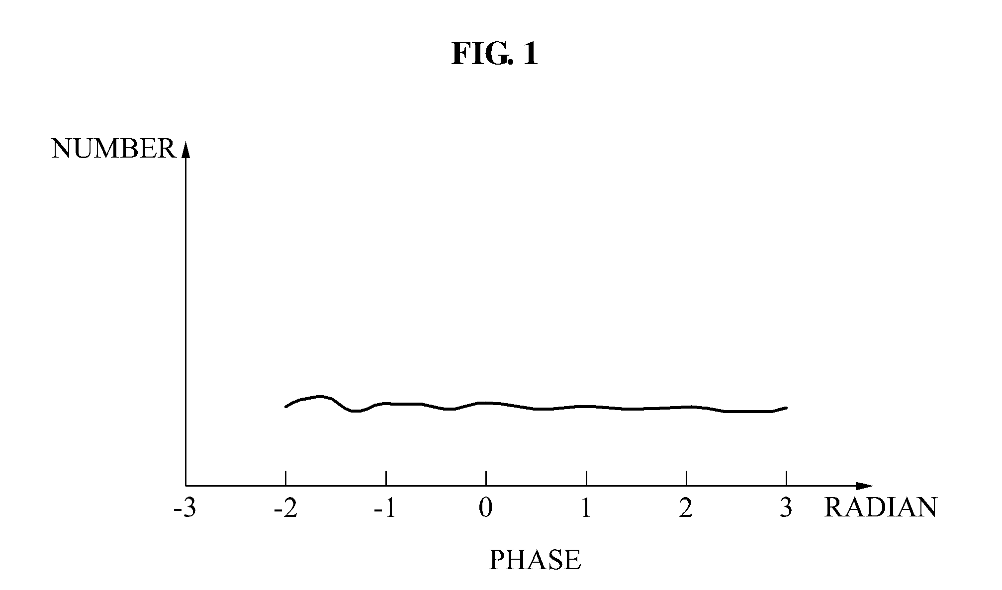
[0034]FIG. 1 is a graph illustrating an example of phase components of input data according to an embodiment of the present invention.

[0035]Referring to FIG. 1, phase components of input data may be assumed to be distributed as illustrated in FIG. 1. Here, since a changing velocity of the phase components may correspond to a frequency, the frequency of the input data may be expressed by performing a first order differentiation with respect to the phase components.

[0036]Hereinafter, the phase components of the input data are indicated by θ, and θn indicates a phase component at an nth time instance.

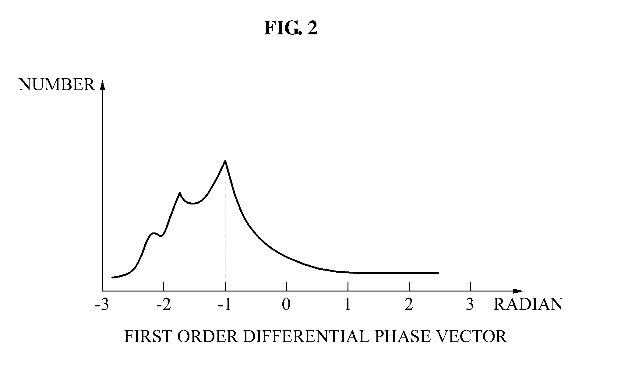
[0037]FIG. 2 is a graph illustrating a first order different...


PUM


Abstract

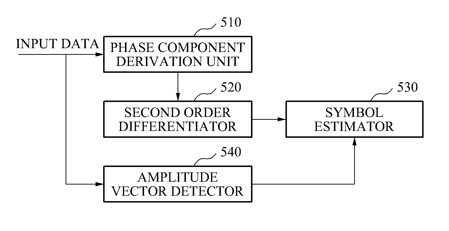
Provided is a method of estimating a symbol. The method may include deriving phase components of input data, applying a second order differentiation to the phase components to obtain a second order differential phase vector, and estimating symbols corresponding to the input data using the second order differential phase vector.

Description

CROSS-REFERENCE TO RELATED APPLICATIONS[0001]This application claims the benefit of Korean Patent Applications No. 10-2009-0125878, filed on Dec. 17, 2009, and No. 10-2010-0010831, filed on Feb. 5, 2010, in the Korean Intellectual Property Office, the disclosures of which are incorporated herein by reference.BACKGROUND[0002]1. Field of the Invention[0003]The present invention relates to an apparatus and method of compensating for a frequency offset and estimating a symbol, and more particularly, to a technique using a second order differential phase vector in a process of compensating for the frequency offset and estimating the symbol.[0004]2. Description of the Related Art[0005]In a general wireless communication system, a receiver may require a function of compensating for a frequency offset in a process of restoring a signal. There exist various algorithms to compensate for the frequency offset. In a case of using a predetermined algorithm to compensate for the frequency offset, ...

Claims


Application Information

Patent Timeline
Patent Type & Authority Patents(United States)
IPC IPC(8): H04L27/06
CPCH04L25/061H04L27/0012H04L27/06H04L27/14H04L27/22H04L2027/0065
Inventor KIM, CHUNG SUPSOHN, SOO HOTAE, KI CHEOLPARK, HYEONG GEUNCHOI
Owner ELECTRONICS & TELECOMM RES INST
Learn More