Shoe

a technology of shoes and linings, applied in the field of shoes, can solve the problems of foam material becoming brittle, being exposed to particularly great stress, and relatively large wear and tear, and achieve the effect of preventing pronation or supination

Active Publication Date: 2013-04-02
BIODYN HLDG BV
View PDF32 Cites 2 Cited by
  • Summary
  • Abstract
  • Description
  • Claims
  • Application Information

AI Technical Summary

Benefits of technology

[0009]With a shoe embodied according to the invention, provided with both insoles and the foam insert sandwiched therebetween, a physiologically correct rolling motion is thus performed such that a rolling motion in the form of a flexing motion is performed beginning, for example, on the outer side of the foot in the rear heel region via the metatarsal region to the ball region and the big toe. As such, the sensitive foam insert between the two insoles is protected not only against mechanical influences, but also against humidity. The wearer of a shoe thus designed will perceive the outside of the shoe as being of a common appearance. This makes the wearer of this shoe feel safe. Nobody can tell that the wearer of a shoe embodied according to the invention is wearing a so-called “balance” shoe.
[0023]This effect is further promoted by the fact that the shoe of the invention is also stable in the lateral direction (“balance” effect”). As a consequence, the wearer / user of this shoe additionally trains (or has to train) the foot muscles, whereby a tendency to pronation or supination is prevented.

Problems solved by technology

The known shoe has proven disadvantageous in that due to the repeated pivotal movement of a part of the sole covering about the axis, the wear and tear are relatively great in the metatarsal region, which consequently is a weak point of this shoe.
Besides, this is no wonder, since this very region, where the pivot axis of the sole covering is located, is exposed to particularly great stresses at each step.
The foam material becomes brittle over time due to the constant high stress it is exposed to, it becomes sensitive to mechanic influences and absorbs any kind of liquid, with the consequence that this foam material has to be removed and replaced with new damping material in a time-consuming operation.

Method used


Image

  • Shoe
  • Shoe
  • Shoe

Examples


Embodiment Construction

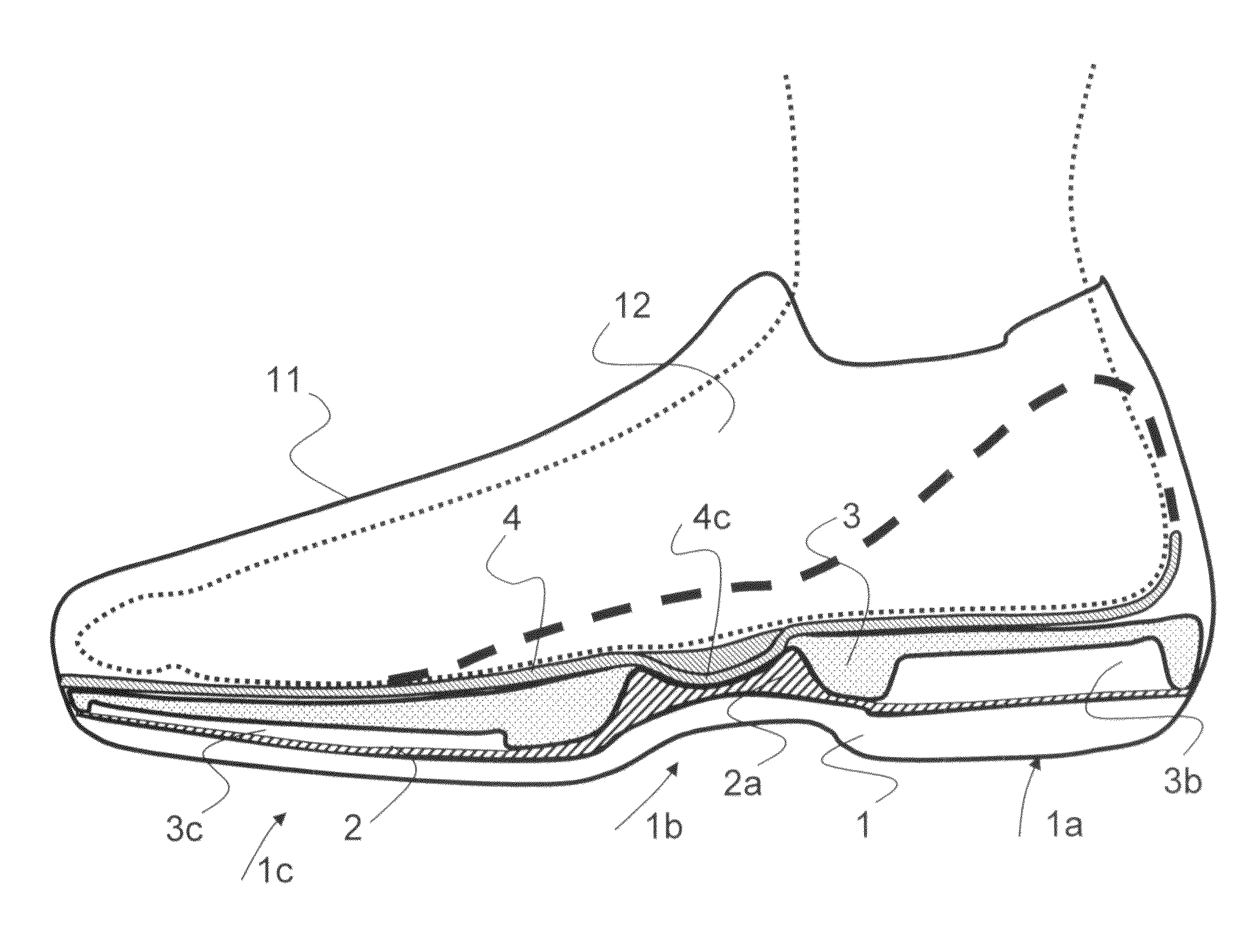
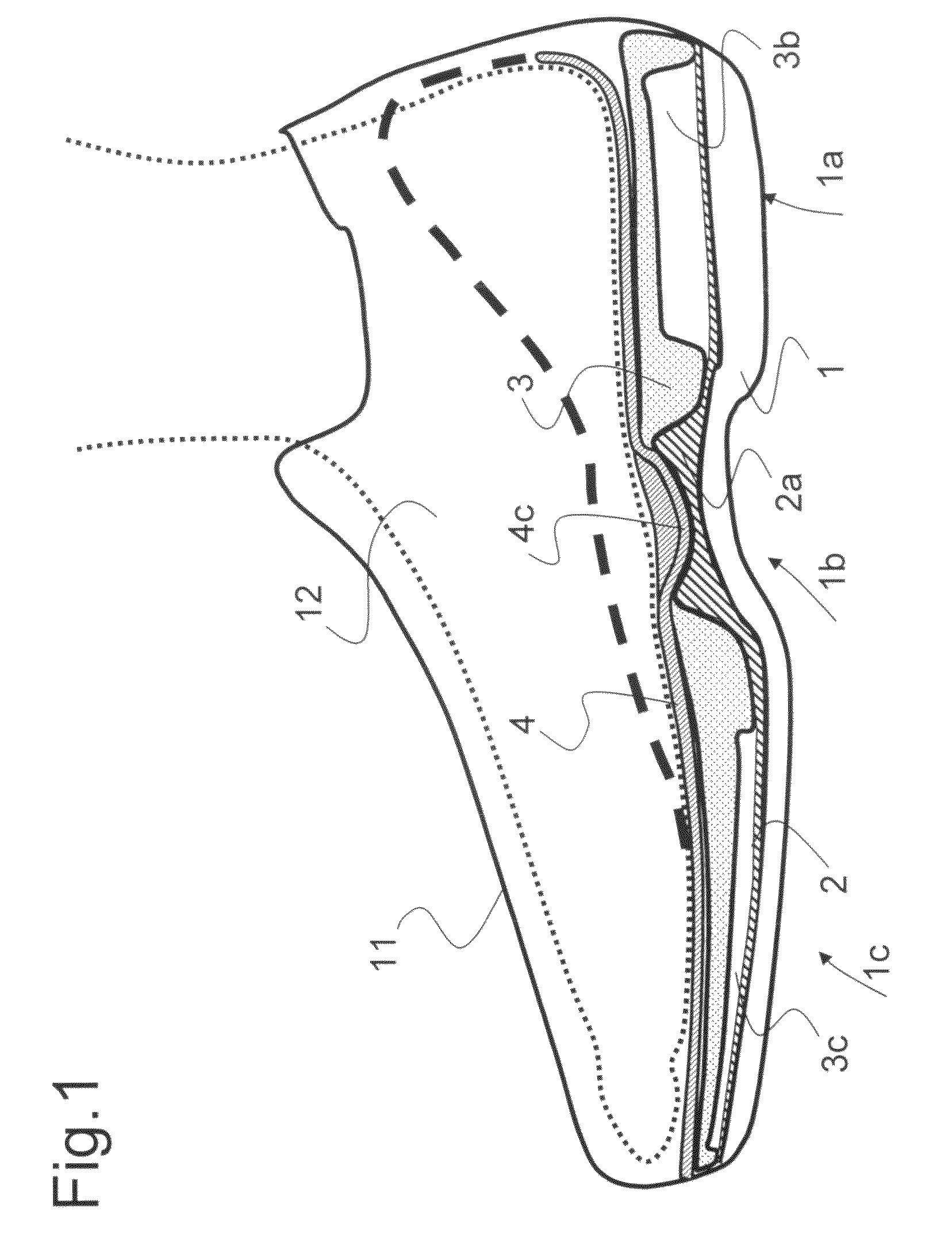
[0032]In FIG. 1 to FIG. 5, identical or similar parts of the shoe of the invention are identified by the same reference numerals. The shoe of the present invention comprises a continuous sole body 1 and upper 11 connected therewith, which encloses a foot 12 of a wearer that is represented in broken lines only in FIG. 1. The upper 11 may be closed in a usual manner, for example, by means of laces, Velcro-type fasteners, or the like. The sole body 1 extends from a rear heel region 1a via a contiguous metatarsal region 1b to a front ball toe region 1c; each of these three regions 1a to 1c extends over approximately one third of the shoe's length.

[0033]A sole covering, not illustrated in detail in the Figures, is provided on the underside of the sole body, which covering is made from an abrasion-resistant material, such as hard rubber, for example, and may be profiled on its underside.

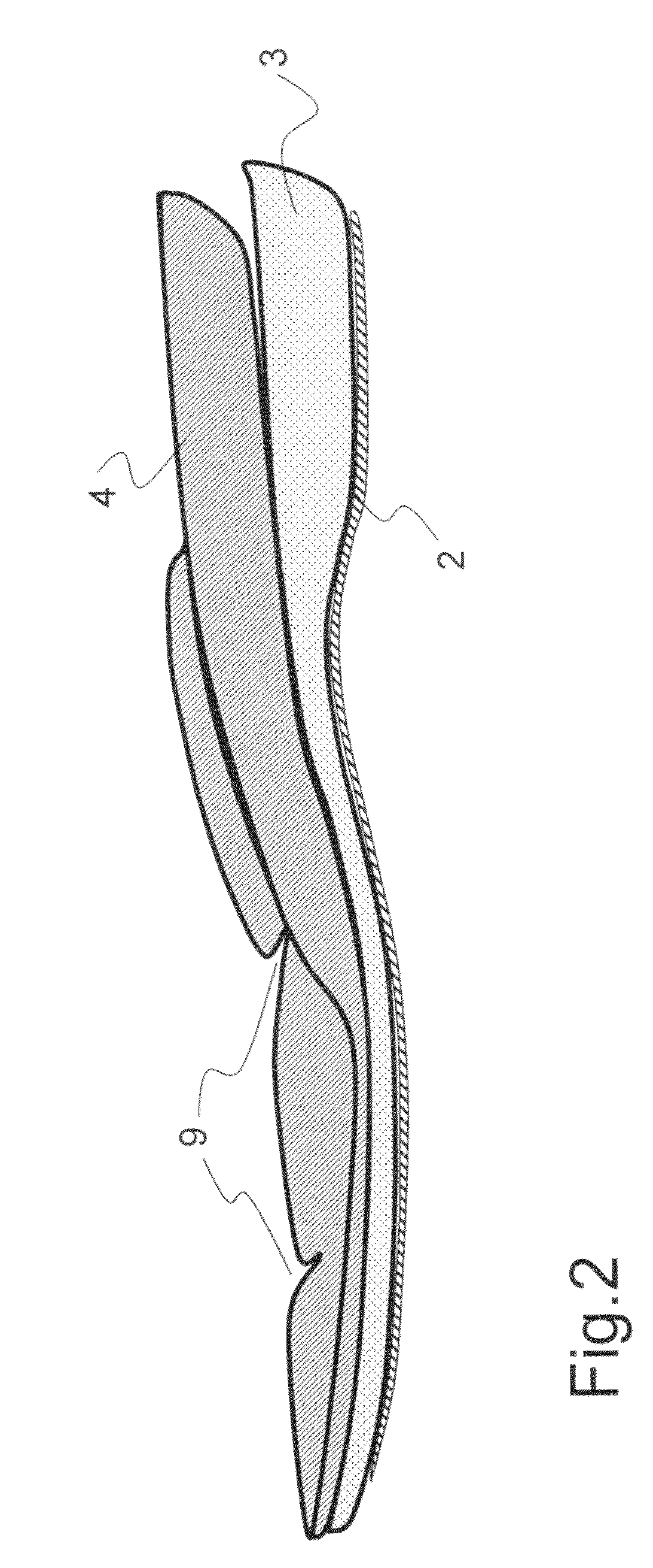
[0034]On the sole body 1, a first thin insole 2 is arranged with an arch insole 2a integrated therein i...


PUM


Abstract

A first thin insole (2) having an arch insole (2a) configured with a recess (2b) in the metatarsal region (1b) is provided on the sole body (1) of a shoe, which extends from the heel region (1a) across the metatarsal region (1b) to the front ball / toe region (1c). A foam insert (3), which has a cutout (3a) corresponding to the size of the arch insole (2a), is disposed on the first insole (2), the insert extending from the heel region (1a) to the front ball / toe region (1c). A second insole (4) in the form of a support, which has a spherical segment-shaped or ellipsoid segment-shaped hollow body (4c), which protrudes in the metatarsal region (1b) from the bottom of the insole (4) and is adapted to the arch insole recess (2b), is provided on the foam insert (3). Such a shoe configured according to the invention can achieve a physiologically effective and correct rolling motion (flexing motion) by the placement of the sole body in the back heel region, and subsequent rolling off via the physiological guide body in the form of the hollow body (4c), toward the front ball / toe region (1c), particularly in the direction of the big toe.

Description

CROSS REFERENCE TO RELATED APPLICATIONS[0001]This application is the National Stage of PCT / EP2007 / 011022 filed on Dec. 14, 2007, which claims priority under 35 U.S.C. §119 of German Application No. 10 2006 059 493.2 filed on Dec. 14, 2006. The international application under PCT article 21(2) was not published in English.[0002]The invention relates to a shoe comprising a sole body extending from the heel region to the front ball / toe region via the metatarsal region, and upper fastened to the sole body.BACKGROUND ART[0003]EP 999 764 describes a shoe with a sole extending from the heel region to the ball / toe region, the sole being formed by a sole body and a sole covering arranged on the underside of the sole body. Further, a recess extending from near the metatarsal region to the heel region is provided between the sole body and the sole covering. The portion of the sole region related to the recess forms a pivot element adapted for pivotal movement about an axis located in the end p...

Claims


Application Information

Patent Timeline
Patent Type & Authority Patents(United States)
IPC IPC(8): A43B13/18
CPCA43B7/14A43B7/142A43B7/143A43B7/144A43B7/1445A43B7/147A43B13/12A43B13/145A43B17/02
Inventor GSCHWENDER, HERBERT
Owner BIODYN HLDG BV
Why Eureka
Try Eureka