
Optical WDM transmitting and receiving device and optical transceiver unit for this device

a technology of optical transceiver and transmitting and receiving device, which is applied in the direction of transmission, transmission monitoring/testing/fault-measurement system, transmission system, etc., can solve the problem that the requirement of correct channel wavelength selection for tunable optical transceiver unit also produces a corresponding expense, and the multiplexer unit cannot integrate the optical signal that is fed on the channel input port. the risk of an incorrect setting of the channel wavelength is reduced or avoided

Active Publication Date: 2013-03-26
ADVA OPTICAL NETWORKING SE
View PDF11 Cites 6 Cited by
  • Summary
  • Abstract
  • Description
  • Claims
  • Application Information

AI Technical Summary

Benefits of technology

The invention provides an optical transceiver unit that can be easily connected to a filter unit of an optical WDM transmitting and receiving device, and reduces the risk of incorrect channel wavelength settings. This prevents incorrect tuning reception signals from being generated by a different transceiver unit on the same side or opposite side of the transmission path.

Problems solved by technology

Here, however, there is the risk that the correct information concerning the channel wavelength to be selected is not transmitted to the controller unit of the optical transmitting unit, for example, because, in the case of the installation of the transceiver unit, the person performing this installation has transmitted incorrect information to the controller unit.
In addition to this risk of incorrect installation of the transceiver unit, for example, on an existing WDM system, the requirement of the correct selection of the channel wavelength for a tunable optical transceiver unit also produces a corresponding expense.
If the channel wavelength of a tunable optical transceiver unit is not selected correctly, then the multiplexer unit obviously cannot integrate the optical signal that is fed on a channel input port and that does not have the correct channel wavelength into the WDM signal to be transmitted.

Method used


Image

  • Optical WDM transmitting and receiving device and optical transceiver unit for this device
  • Optical WDM transmitting and receiving device and optical transceiver unit for this device

Examples


Embodiment Construction

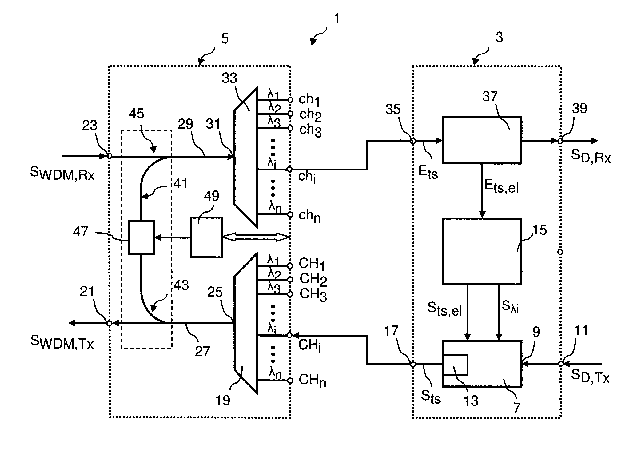
[0036]The WDM transmitting and receiving device 1 shown in the single FIGURE comprises an optical transceiver unit 3 and an optical filter unit 5.

[0037]The optical transceiver unit 3 has an optical transmitting unit 7 to which an electrical data signal SD, Tx can be fed via a data signal port 9. For this purpose, the transceiver unit 3 may also have a data signal port 11. The optical transmitting unit 7 comprises an optical transmitting module 13 that can be tuned with respect to its optical carrier wavelength. In normal operating mode, the optical transmitting unit 7 converts the data signal SD, Tx fed to it into a corresponding optical data signal. The optical transmitting unit may also perform necessary signal conditioning or signal processing.

[0038]For this purpose, a controller unit 15 of the transceiver unit 3 drives the transmitting unit 7 so that a signal with a specified optical carrier wavelength is output on an output port 17 of the transceiver unit 3. For this purpose, t...


PUM


Abstract

An optical transceiver unit for an optical WDM transmitting and receiving device is taught, with a transmitting unit to which a data signal can be fed to a specified channel input port of a multiplexer unit, wherein a separate channel wavelength is allocated to each channel input port, and the transmitting unit can be tuned with respect to optical carrier wavelength across a specified range of wavelengths. The transmitting unit is constructed so that, within the specified range of wavelengths, discrete wavelengths can be set that correspond to the channel wavelengths. In tuning mode, the controller unit can drive the transmitting unit so that the possible channel wavelengths are scanned through. The controller unit evaluates the reception signal fed to it from the receiving unit for whether abort criteria for tuning mode have been fulfilled or not, wherein the scanning process is continued until the abort criteria are fulfilled.

Description

FIELD OF THE INVENTION[0001]The invention relates to an optical transceiver unit for an optical WDM transmitting and receiving device. In addition, the invention relates to an optical WDM transmitting and receiving device with such an optical WDM transceiver unit.BACKGROUND[0002]Optical wavelength division multiplexing systems (WDM systems) are used in optical transmission networks in order to transmit large volumes of data. In a network node or a terminal node of a simple point-to-point connection, an optical filter unit is provided that comprises at least one optical multiplexer unit and one optical demultiplexer unit. The optical multiplexer unit has a specific number n of channel input ports, and feeds optical channel signals fed to the channel input ports to a WDM output port, wherein the optical channel signals can be combined into one WDM signal. The optical demultiplexer unit has a WDM input port to which the WDM signal to be received is fed. The multiplexer unit splits the ...

Claims


Application Information

Patent Timeline
Patent Type & Authority Patents(United States)
IPC IPC(8): H04J14/02G02B6/28
CPCH04J14/0227H04J14/02H04J14/0257H04J14/0258H04J14/0305
Inventor HINDERTHUR, HENNINGBLECK, OLIVER
Owner ADVA OPTICAL NETWORKING SE
Learn More