
Sample trituration vessel, tool and method using the same

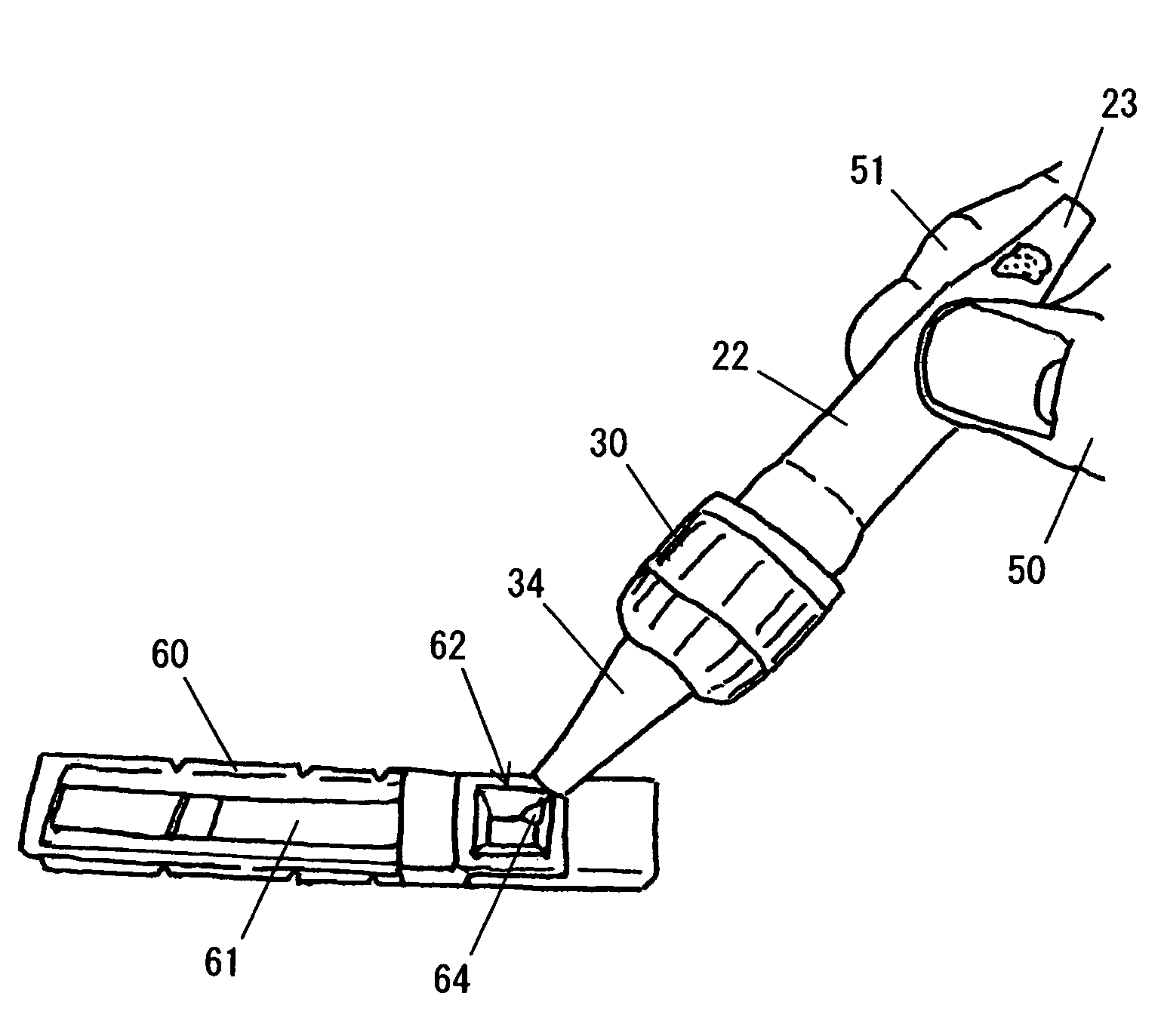
a trituration vessel and sample technology, applied in the field of sample trituration vessels, can solve the problems of large space needed for trituration, increased sample loss, and possible fall in detection accuracy, and achieve the effects of high efficiency, excellent portability, and high efficiency

Active Publication Date: 2013-03-26
MIZUHO MEDY
View PDF15 Cites 1 Cited by
  • Summary
  • Abstract
  • Description
  • Claims
  • Application Information

AI Technical Summary

Problems solved by technology

When there are many samples, a large space is needed for trituration thereof.
The sample easily tends to be attached to the outer surfaces of the mortar and pestle, thereby increasing loss of the sample.
When the sample is very little, fall of detection precision may be caused.
The set of the mortar and pestle is expensive (about 500 Japanese Yen).
As described in detail later, however, experiments by the inventors prove that the efficiency of trituration according to this example is not enough when the sample is relatively hard.
Inspection by the inventors, however, indicates that the bag may be broken according to a condition of pressure when trituration is carried out.

Method used


Image

  • Sample trituration vessel, tool and method using the same
  • Sample trituration vessel, tool and method using the same
  • Sample trituration vessel, tool and method using the same

Examples


embodiment 1

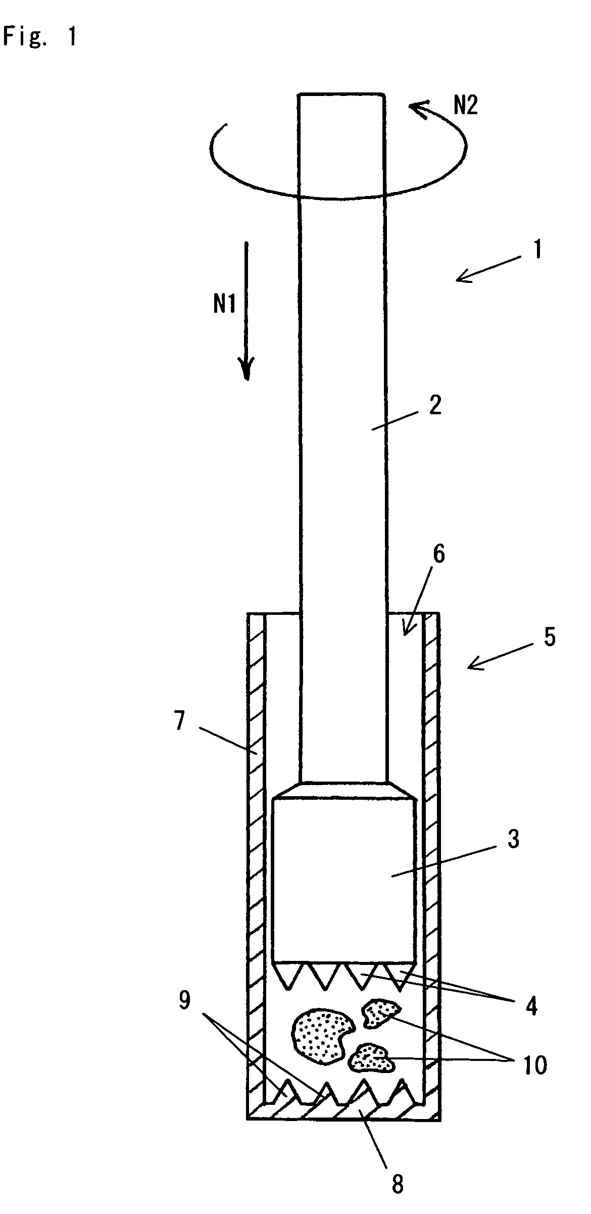
[0043]Embodiments of the present invention will now be explained referring to the attached drawings. FIG. 1 is a sectional view of a sample trituration vessel in Embodiment 1 of the present invention.

[0044]As illustrated in FIG. 1, a sample trituration tool of Embodiment 1 is equipped with a trituration rod 1 and a sample trituration vessel 5.

[0045]The trituration rod 1 comprises: a rod body 2 having a cylindrical and tapered shape; and a head portion 3 provided at a lower end of the rod body 2. A rugged portion 4 is formed at a lower end of the head portion 3. The rugged portion 4 is composed of a plurality of protrusions.

[0046]The sample trituration vessel 5 is equipped with a tubular body 7. The tubular body 7 has an opening 6 at an upper end and a bottom part 8 at a lower end, respectively. The tubular body 7 is formed in a manner such that the head portion 3 of the trituration rod 1 can be inserted therein. A rugged portion 9 is formed on an upper surface of the bottom portion ...

embodiment 2

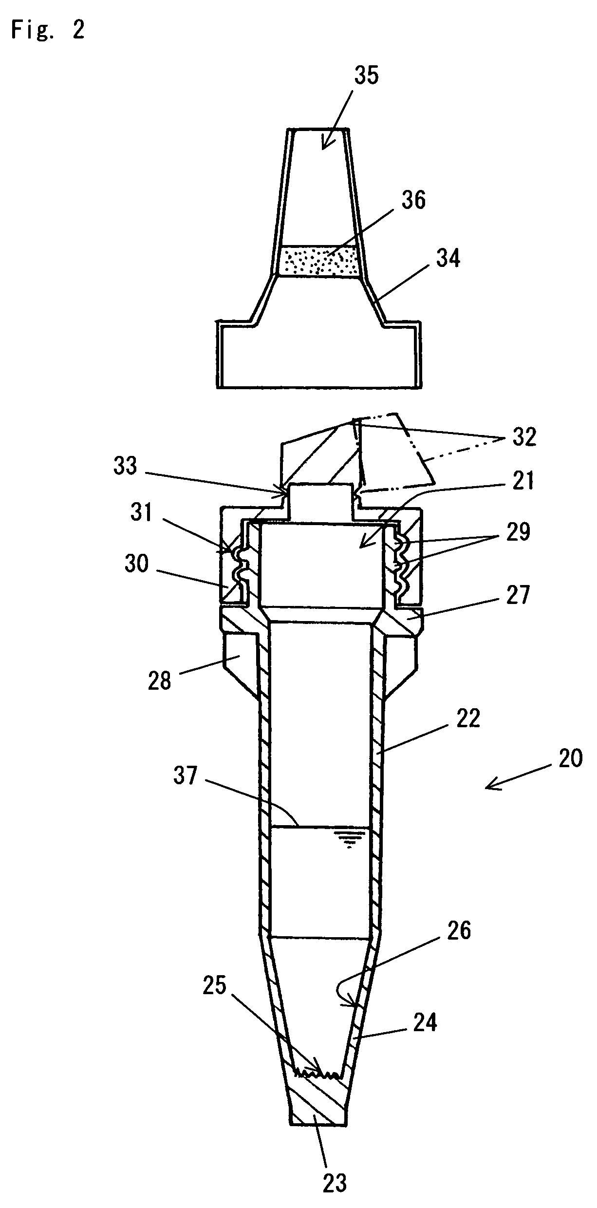
[0049]FIG. 2 is a sectional view of a sample trituration vessel in Embodiment 2 of the present invention, and FIG. 3 is a front view of a trituration rod in the same.

[0050]As illustrated in FIG. 3, a trituration rod 40 of this Embodiment is equipped with a cylindrical and tapered rod body 41, and a head portion 43 provided at a lower end of the rod body 41. A first rugged portion 44 is formed at a lower end of the head portion 43. The first rugged portion 44 is composed of a plurality of protrusions. A slanted surface of the head portion 43 has a shape of a cone becoming narrow downward (that is, tapering off). A plenty of grooves are cut on the surface to form a second rugged portion 45. A plurality of vertical grooves arc is cut on an upper part of the rod body 41 to form a gripping part 42. Thereby, a hand of an operator gripping the trituration rod 40 is hard to slip.

[0051]As illustrated in FIG. 2, the sample trituration vessel of this Embodiment is equipped with a sample tritur...


PUM

PropertyMeasurementUnit
diameteraaaaaaaaaa
flexibleaaaaaaaaaa
shapeaaaaaaaaaa

Abstract

There is provided a sample trituration vessel that even when the sample is relatively hard, enables triturating of the sample easily and with high efficiency. The sample trituration vessel includes a tubular body having an opening at one end and having a bottom part at the other end thereof. The tubular body is furnished with a rugged portion there-inside so as to be able to meet another rugged port formed on a trituration rod. The sample trituration vessel itself can exert shearing effect on the sample. The tubular body is formed of flexible material, and upon application of external force from outside of the tubular body, the tubular body is deformed, thereby breaking down the sample held within the tubular body.

Description

BACKGROUND OF THE INVENTION[0001]I. Technical Field[0002]The present invention relates to a sample trituration vessel for triturating an organic sample derived from an animal or a plant therein with high efficiency, and art related thereto. To be more specific, the present invention is suitable for triturating a sample relatively hard (for example, plant-leaves immersed in buffer). In a preferable example, the present invention is suitable for a case where an orange farmer triturates a sample (for example, leaves of an orange) in or near his / her orange field in order to detect whether or not the orange is suffered from a specific disease.[0003]II. Description of the Related Art[0004]The immunochromatography method is frequently used as technology of qualitatively or quantitatively analyzing a substance to be detected in a liquid sample (especially, in an organic ingredient) in view of simple and rapid operation of the method. More concretely, a substance, which is specific to both l...

Claims


Application Information

Patent Timeline
Patent Type & Authority Patents(United States)
IPC IPC(8): G01N33/48G01N33/487
CPCG01N1/286G01N2001/2866B02C19/08
Inventor MIMORI, TOMOHIRONARAHARA, KENJI
Owner MIZUHO MEDY
Learn More