
Two stage radio frequency interference cancellation system and method

a radio frequency interference and cancellation system technology, applied in the field of radio receiver systems and methods, can solve the problems of unsatisfactory input distortion, limited input capacity, loss of sensitivity, etc., and achieve the effect of avoiding receiver saturation, reducing interference, and reducing interferen

Active Publication Date: 2013-03-19
HYPRES
View PDF9 Cites 30 Cited by
  • Summary
  • Abstract
  • Description
  • Claims
  • Application Information

AI Technical Summary

Benefits of technology

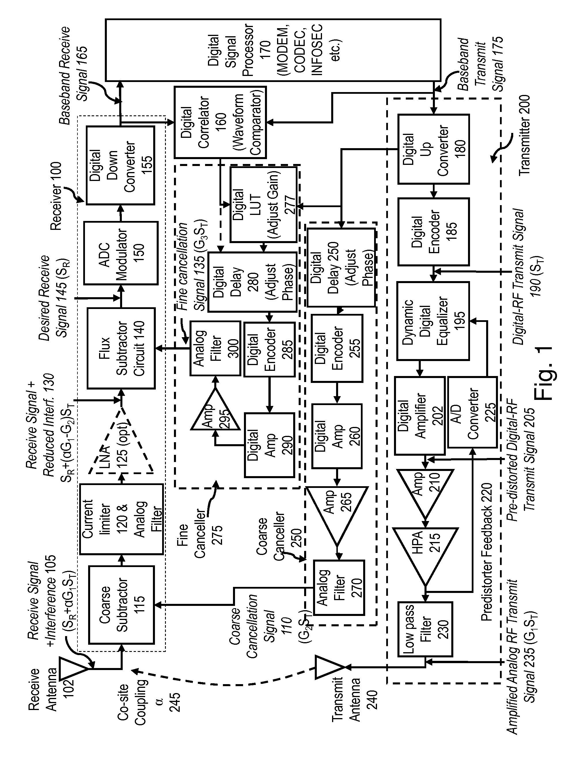
[0010]The present invention provides a self-calibrating, two stage interference cancellation architecture for mitigating interference present in a wideband receiver, and especially which avoids saturation of the receiver, or even damage to the receiver, by strong interferors.
[0013]The two stage architecture provides an advantage in that the first stage is adapted to avoid irreversible distortion of the signal of interest while maintaining an amplitude of the interferor below a saturation or damage level for the input circuitry.
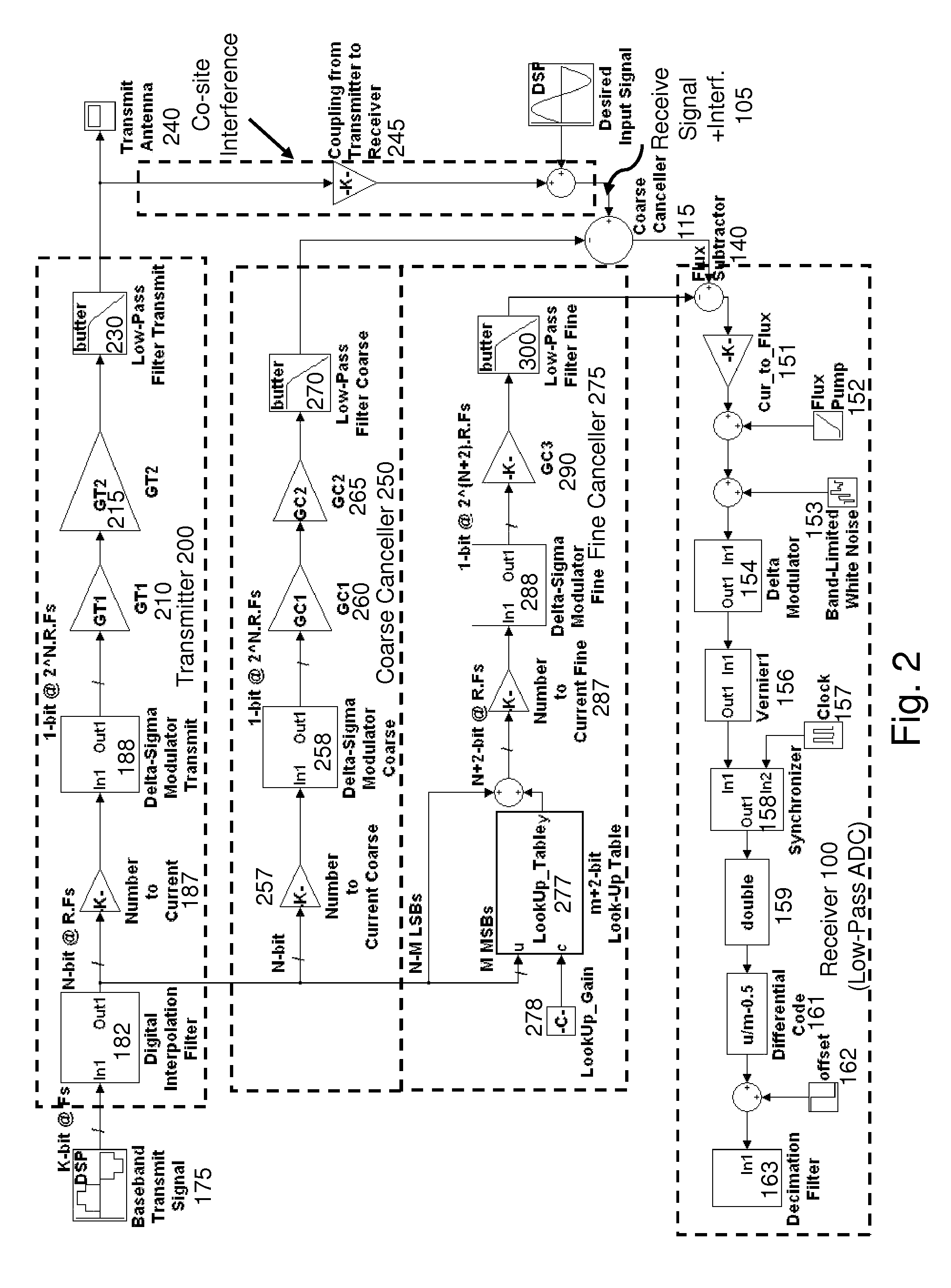
[0017]According to a preferred embodiment of the invention, a model of an interfering signal, for example a co-site interferor for which the data which generates the transmitted waveform is available, is used to generate a corresponding signal which is subtracted from a received signal. In particular, the invention provides a two-stage interference cancellation system, having a first stage which precedes active circuits within the receiver, and thereby reduces signal overload and permits high gain, and a second stage which is provided after amplification of the difference signal resulting from the first stage.
[0019]Since the first stage occurs prior to amplification or other processing, the cancellation signal is established to reduce the level of the resulting signal such that it does not saturate or damage remaining components of the system, and since there is a second stage, the cancellation does not have to be complete. Further, by reducing the interferor amplitude prior to passing through non-linear processing elements, such as semiconductor amplifiers, the level of intermodulation distortion is decreased.
[0020]Typically, the first stage cancellation signal represents a model of the interfering signal, which may be, for example, a representation of the source data for that signal and an interference signal path model, which for example can account for transmitter distortion, multipath, and the like. On the other hand, the second stage can be adaptively driven based on the downstream signal, less dependent on the interfering signal per se, since the output of the second stage is within the dynamic range of the receiver, permitting digital processing of the resulting signal after the second stage. Therefore, the first stage seeks to grossly cancel the interfering signal, while the second stage addresses residual components. Generally, the second stage accepts signals which are within the operating range of the circuit technology, but possibly outside the saturation range of the receiver, and produces a signal within the operating range of the receiver. The first stage, since it precedes active components, has a much larger operating range with respect to received signals, without damage or substantial distortion.

Problems solved by technology

In sensitive radio frequency receivers, the use of input protection devices may cause undesired distortion of the input, or loss of sensitivity.
Therefore, a strong signal is passed directly to a sensitive input device, which may have limited input capacity.
In either case, the net result is to pass a signal to the electronic input stages which is within the capacity of those stages to handle, wherein the signal may still retain partial interference and even possible distortion from the first cancellation process.

Method used


Image

  • Two stage radio frequency interference cancellation system and method
  • Two stage radio frequency interference cancellation system and method
  • Two stage radio frequency interference cancellation system and method

Examples


Embodiment Construction

[0066]Two-Stage Hybrid Temperature Hybrid Technology Cancellation Architecture

[0067]The two stage hybrid temperature hybrid technology (HTHT) architecture as shown in FIG. 1 seeks to accomplish two significant goals:

[0068]Provide a high precision cancellation with greater than 80 dB reduction of high power interference in the 0-30 MHz band.

[0069]Nulling the bulk of the interference in a coarse canceller at a high temperature stage. This facilitates employing a current limiting device to protect the quantizer from being permanently damaged by any high power currents that may result in event of unsuccessful cancellation.

[0070]One of the advantages of the two-stage cancellation architecture is the increased flexibility in tuning the gain of the cancellation signal. The increased flexibility comes from the fact that the total gain of the amplifier chain, in the coarse and fine cancellation paths, can be independently adjusted to change their respective outputs on a coarse and fine grid ...


PUM


Abstract

A radio frequency receiver subject to a large in-band interferor employs active cancellation with coarse and at least one cancellation signals, each with a respective radio frequency combiner, in order to increase the effective dynamic range of the receiver for weak signals of interest. One or both can be digitally synthesized. This is particularly applicable for co-site interference, whereby the interfering transmit signal is directly accessible. A similar system and method may also be applied to external interferors such as those produced by deliberate or unintentional jamming signals, or by strong multipath signals. An adaptive algorithm may be used for dynamic delay and gain matching. In a preferred embodiment, a hybrid technology hybrid temperature system incorporates both superconducting and semiconducting components to achieve enhanced broadband performance.

Description

CROSS REFERENCE TO RELATED APPLICATIONS[0001]The present application is a Continuation of U.S. patent application Ser. No. 12 / 535,843, filed Aug. 5, 2009, which issued as U.S. Pat. No. 8,249,540 on Aug. 21, 2012, which is a Nonprovisional of and claims benefit of priority from U.S. Provisional Patent Application 61 / 087,162, filed Aug. 7, 2008, each of which is expressly incorporated herein by reference in its entirety.STATEMENT OF GOVERNMENT RIGHTS[0002]This invention was made with government support under U.S. Navy contract # N00039-08-C-0022 awarded by The U.S. Navy. The government has certain rights in the invention.FIELD OF THE INVENTION[0003]The present invention relates to the field of radio receiver systems and methods, and more particularly to receivers which are tolerant of high levels of in-band interference.BACKGROUND OF THE INVENTION[0004]Radio receivers are well known. Typically, systems are designed to avoid strong interferors in the received band, or provide sufficien...

Claims


Application Information

Patent Timeline
Patent Type & Authority Patents(United States)
IPC IPC(8): H04B1/10
CPCH04B1/109H04L27/01H04B7/15585H04B1/525H04B1/10
Inventor GUPTA, DEEPNARAYANINAMDAR, AMOL
Owner HYPRES
Learn More