
Powertrain comprising an optimized energy recovery system

a powertrain and energy recovery technology, applied in the direction of battery/cell propulsion, capacitor propulsion, gearing, etc., can solve the problems of unfeasible use of toxic or explosive materials, waste of energy used to drive the vehicle, and inability to reduce the energy demand, so as to improve the efficiency ratio, reduce the size of the system, and improve the integration

Active Publication Date: 2013-03-19
VOLVO LASTVAGNAR AB
View PDF18 Cites 28 Cited by
  • Summary
  • Abstract
  • Description
  • Claims
  • Application Information

AI Technical Summary

Problems solved by technology

When analyzing the balance of energy used to operate a vehicle, there is a non reducible energy demand due to the drag and rolling forces that are intrinsic characteristics of the vehicle.
This one being put apart, an amount of the energy which is used to drive the vehicle is wasted in the brakes, coming from potential energy kinetic energy (resulting from the energy provided to the vehicle when accelerating), and potential energy (resulting from energy provided to the vehicle during hill climbing).
Compared to electrochemical batteries, flywheels are likely to be an economic alternative when:rapid discharge and recharge are necessary;long life cycle is necessary;weight or volume is constrained;use of toxic or explosive materials is unfeasible; and / orenvironmental control is difficult.
When high energy capacities are needed, flywheels must rotate at high speeds with safety issues (risk of burst of the flywheel due to inertia forces) and technological issues (such as issues with the bearing).
Although electric machines have inherently good efficiency ratios, these numerous transformations necessarily lead to energy losses.
Nevertheless, this layout has some drawbacks.

Method used


Image

  • Powertrain comprising an optimized energy recovery system
  • Powertrain comprising an optimized energy recovery system
  • Powertrain comprising an optimized energy recovery system

Examples


first embodiment

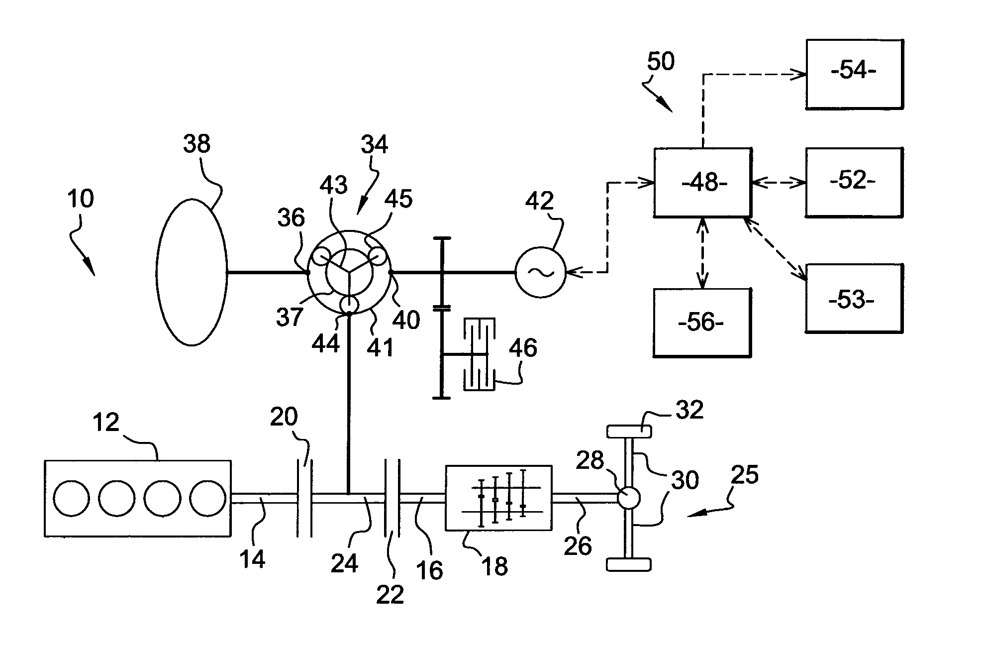
[0053]In this first embodiment of the invention shown on FIG. 1, the powertrain 10 has no active loads. As will be seen, all the energy which is used to run the first 42 electric machine comes from the electrical storage 52. The powertrain 10 must thus be tuned in order to reduce the rating of the electrical storage (in terms of capacity and of charging / discharging power) through a proper choice of the characteristics of the transmission and of the planetary gear 34.

[0054]The powertrain 10 according to the invention has different operating modes, some of which are described below, with reference to FIGS. 10 to 14b

[0055]FIGS. 10, 11a, 12a, 13a, 14a are based on the conventional speed diagram of a planetary gear. In the example shown, it is recalled that the sun wheel 37 is coupled to the flywheel 38, the ring wheel 41 is coupled to the first electrical machine 42 and the carrier 43 is coupled to the engine 12. On such a speed diagram the three vertical axis S, C, R represent respect...

second embodiment

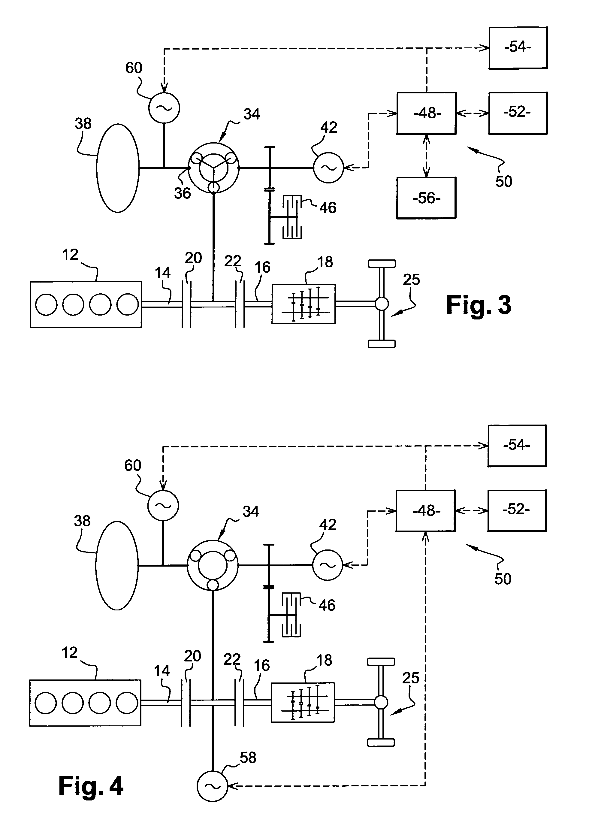
[0068]As in the second embodiment, the third electric machine 60 can be used to transfer energy from one storage means to the other, in order to manage their state of charge independently.

[0069]The third electric machine 60 can also assist the batteries to operate the first electrical machine by using an amount of energy from the flywheel 38. At last, the third electric machine 60 can be rated in order to provide most of the energy to operate the first electrical machine 42, so that the size of the batteries can be minimized.

[0070]The fourth embodiment shown on FIG. 4 is simply a combination of the second and third embodiments, with both the second 58 and the third 60 electrical machines as described above. This embodiment has the advantage of allowing an optimum and flexible management of the energy recovery, optimizing the use and storage of the energy. This embodiment enables to transfer part of the energy in electric mode to and from the flywheel.

[0071]In all the cases above, it...


PUM


Abstract

A powertrain includes a variable ratio transmission device having an input shaft coupled to an engine and an output shaft coupled to a driven unit, a three-way power split transmission device including three input / output couplings, a first of which is coupled to a flywheel and a second of which is coupled to an electrical machine. The third input / output coupling of the three way power split transmission device is mechanically coupled to the engine and to the input shaft of the variable ratio transmission device.

Description

BACKGROUND AND SUMMARY[0001]The invention relates to a powertrain equipped with an optimized energy recovery system comprising a flywheel.[0002]The reduction of the fuel consumption is a major stake for the sustainability of many industries, but most important for the automotive industry and the machinery industry. A huge majority of vehicles (trucks, buses, passenger cars, etc.) is fitted with a powertrain comprising an internal combustion engine which drives the driving wheels through a transmission set (including for example a clutch or a torque converter, a manual, automated or automatic gearbox, a differential, an axle) and on another part the auxiliaries that are necessary to operate the vehicle systems. Some of these auxiliaries are fed by an electrical network, which energy comes from a generator run by the ICE. In the case of commercial vehicles, the engine is most often a turbo-charged diesel engine. Similar powertrains are used to power all sorts of machines, including co...

Claims


Application Information

Patent Timeline
Patent Type & Authority Patents(United States)
IPC IPC(8): F16H3/72F16H37/06B60K6/445B60L50/16
CPCB60K6/105B60K6/30B60K6/365B60K6/40B60K6/48B60K6/547Y10T74/19023Y02T10/6204Y02T10/6221Y02T10/6282Y02T10/92B60L7/04B60L7/08B60L7/12B60L7/22B60L15/2009B60L15/2045B60L15/2054B60L2240/36B60L2240/421B60L2240/423B60L2240/441B60L2240/443B60L2240/486Y02T10/72B60L50/40B60L50/61B60L50/16B60L50/30B60L58/12B60L58/21Y02T10/62Y02T10/70Y02T10/64Y02T10/7072
Inventor SARTRE, VINCENTJUSTIN, THOMAS
Owner VOLVO LASTVAGNAR AB
Learn More