Stringing block for aerial electric conductor

a technology of aerial electric conductors and stringing blocks, which is applied in the direction of cable installation apparatus, pipe-laying vessels, portable lifting, etc., can solve the problems of relatively light pilot lines, heavy frame load, and inability to support helicopter stringing

Inactive Publication Date: 2013-03-19
TUKACHINSKY ARIE LEIB
View PDF10 Cites 9 Cited by
  • Summary
  • Abstract
  • Description
  • Claims
  • Application Information

AI Technical Summary

Benefits of technology

[0012]It is an object of the invention to provide a stringing block, intended for hanging to electrical line structures, insulators etc., suitable for both manual and helicopter pilot line or conductor stringing, the block should be light enough for to prevent conductor / pilot line escaping the shave groove and friction on the shave flange. The invention achieves this by using a ring-shaped sheave, running over one or two small wheels, installed on a small size frame and rotating around their axles.
[0017]This stringing block configuration enables a light weight frame with its centre of gravity close to the hanging point, and light weight shaves. Additionally, shifting of the block hanging point from the centre plane of the sheave groove helps to balance the moment of the net conductor tension at angle line structures. In combination, it solves said problems.

Problems solved by technology

The frame is heavily loaded, especially at the blocks for helicopter stringing or for bundled conductor installation, and, accordingly, heavy weighting.
A significantly lighter stringing block is disclosed in the U.S. Pat. No. 4,201,369 by Betta, but it doesn't support helicopter stringing.
It causes two main problems:a) The relatively light pilot line has a tendency to escape the groove of a sheave of the stringing block.
But since the weight of the pilot line is different from that of the conductor, and the tension is variable through the pulling process, fixing the block position exacerbates the second problem, increasing the conductor friction on the sheave flange.
But a dominant opinion is that the conductor is strongly bended and unbended on each single roll, and damaged; as a result, many conductor suppliers explicitly forbid using these blocks with their conductors.
One problem with this block is that sensible cables cannot run on rolls (Page points that this block is intended for heavy cables).
Another one is that it doesn't support helicopter stringing.

Method used


Image

  • Stringing block for aerial electric conductor
  • Stringing block for aerial electric conductor
  • Stringing block for aerial electric conductor

Examples


Embodiment Construction

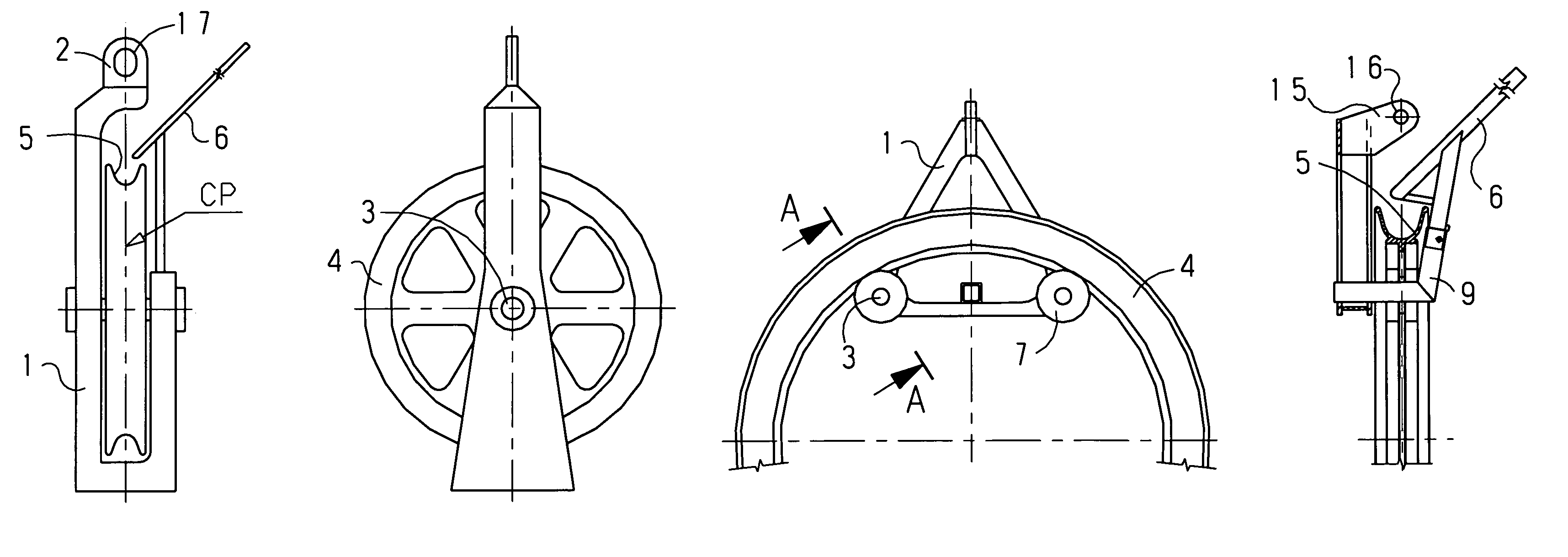
[0027]FIG. 1 shows a typical previous art stringing block, suitable for helicopter stringing, front and side views. Some details, insignificant for this description, are omitted for clearness. The block comprises a frame 1 with hanging means 2. An axle 3 is fixed to the frame 1 at its both ends. A shave 4 is mounted on the axle centrally via two bearings (not shown). The outer side of the shave is grooved; the groove profile 5 is suitable for stringing and pulling a single conductor. The hanging eye 17 is placed at the groove centre plane CP. A guide arm 6 is fixed at the open side of the frame for to accept a pilot line from a helicopter and direct it into the shave groove. When pulling the pilot line, and then the conductor, the shave rotates around the axle, and the conductor runs within the groove.

[0028]FIG. 2 shows a stringing block in accordance to the current invention, front and side views. This block is also intended for a single conductor and suitable for helicopter string...


PUM

PropertyMeasurementUnit
weightaaaaaaaaaa
frictionaaaaaaaaaa
tensionaaaaaaaaaa

Abstract

A stringing block for aerial electric conductor or other aerial cable, intended for hanging to electric line structures, insulators etc., suitable for both manual and helicopter pilot line or conductor stringing, is disclosed. The block comprises one or more ring-shaped sheaves, each one running over one or two small wheels, installed on a small size frame and rotating around their axes. The block is light enough for to prevent conductor / pilot line escaping the shave groove and friction on the shave flange.

Description

FIELD OF THE INVENTION[0001]This invention relates to stringing blocks for conductors installation at overhead electrical transmission and distribution lines or any other aerial cables installation.BACKGROUND OF THE INVENTION[0002]For pulling conductors at overhead transmission and distribution lines, stringing blocks are installed at the line structures. A pilot line is stringed through the blocks, either manually or by a helicopter. Then, the pilot line is exchanged by a single or bundled conductor, running on the blocks. Finally, the conductor is sagged and then transferred from the blocks to clamps.[0003]The most of existing blocks consist of one or more sheaves, installed on an axle via bearings, the axle is supported by a frame, suitable for to be hanged to a line structure or an insulator. The frame is heavily loaded, especially at the blocks for helicopter stringing or for bundled conductor installation, and, accordingly, heavy weighting. Some kinds of stringing blocks are d...

Claims


Application Information

Patent Timeline
Patent Type & Authority Patents(United States)
IPC IPC(8): H02G1/02
CPCB66D3/06Y10T29/49826
Inventor TUKACHINSKY, ARIE LEIB
Owner TUKACHINSKY ARIE LEIB
Why Eureka
Try Eureka