
Separation and contrast enhancement of overlapping cast shadow components and target detection in shadow using polarization

a technology of contrast enhancement and component, applied in the field of image processing, to achieve the effect of simplifying processing, and improving contrast within shadows of imaged scenes

Active Publication Date: 2013-03-12
THE TRUSTEES OF THE UNIV OF PENNSYLVANIA
View PDF8 Cites 8 Cited by
  • Summary
  • Abstract
  • Description
  • Claims
  • Application Information

AI Technical Summary

Benefits of technology

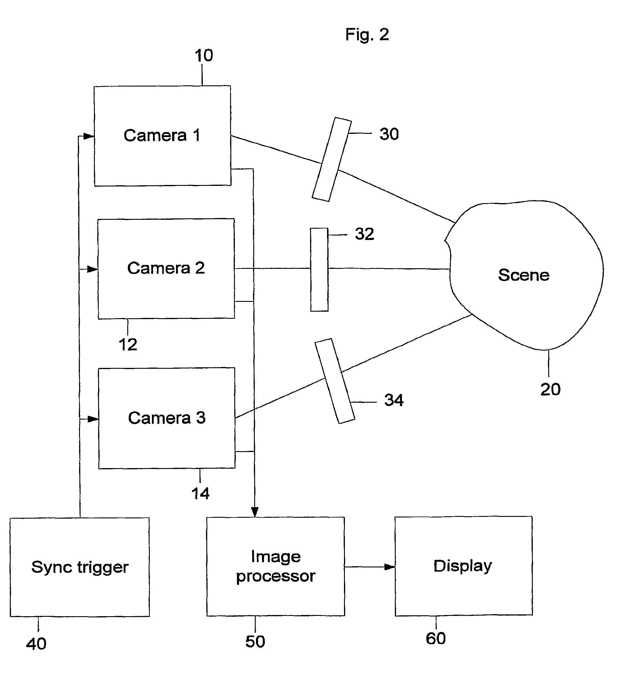
The present invention is a method and system for improving the contrast within shadows of an imaged scene. The method involves obtaining images of the scene from at least three different angles using a polarization analyzer attached to a camera. The intensity of the light is measured at each pixel and is calculated as a function of the angle at which the analyzer is oriented. The resulting images provide information on the orientation of the light in the scene. If the intensity is non-zero, a p image may also be recovered and displayed. In an exemplary embodiment, the method includes calculating a measure of the linear polarization at each pixel, which can be used to enhance the contrast of the image. The system includes a polarization analyzer, cameras, and software to process the images and enhance them. Overall, the invention improves the visibility and quality of shadows in images.

Problems solved by technology

Such differences in intensity and color create patterns and boundaries / edges that often confuse human observers or machine vision algorithms that attempt to segment scenes and identify objects using these cues.
However, all previously published methods use only two aspects of light—its intensity and / or spectral (“color”) distribution—as information in shadow segmentation.

Method used


Image

  • Separation and contrast enhancement of overlapping cast shadow components and target detection in shadow using polarization
  • Separation and contrast enhancement of overlapping cast shadow components and target detection in shadow using polarization
  • Separation and contrast enhancement of overlapping cast shadow components and target detection in shadow using polarization

Examples


Embodiment Construction

[0023]The invention will be described in detail below with reference to FIGS. 1-16. Those skilled in the art will appreciate that the description given herein with respect to those figures is for exemplary purposes only and is not intended in any way to limit the scope of the invention. All questions regarding the scope of the invention may be resolved by referring to the appended claims.

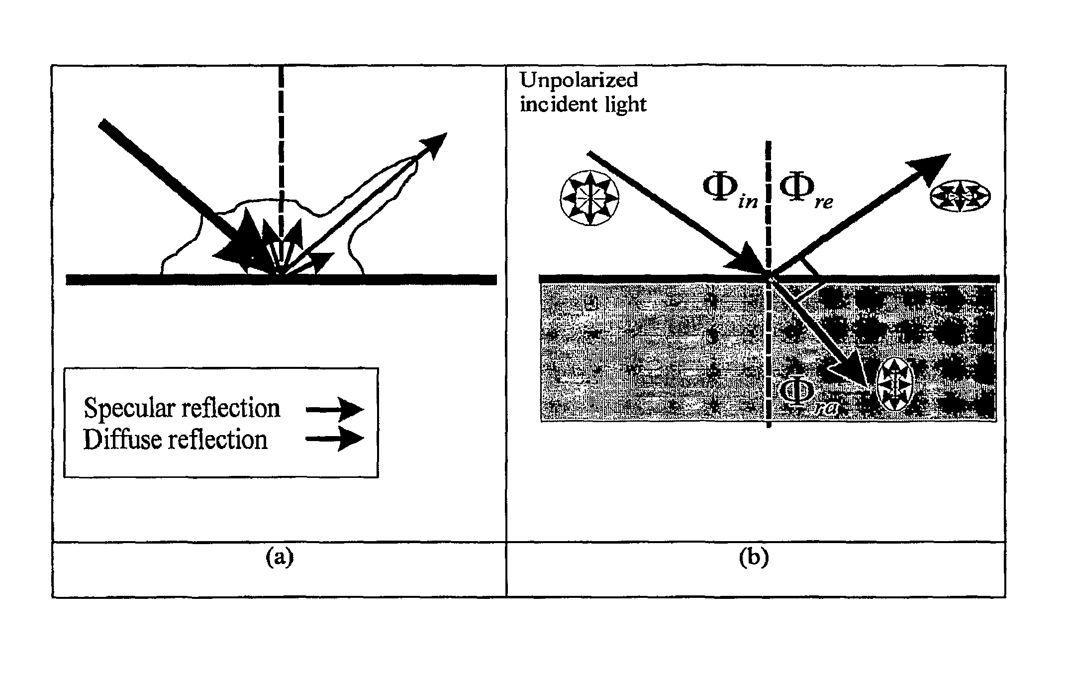
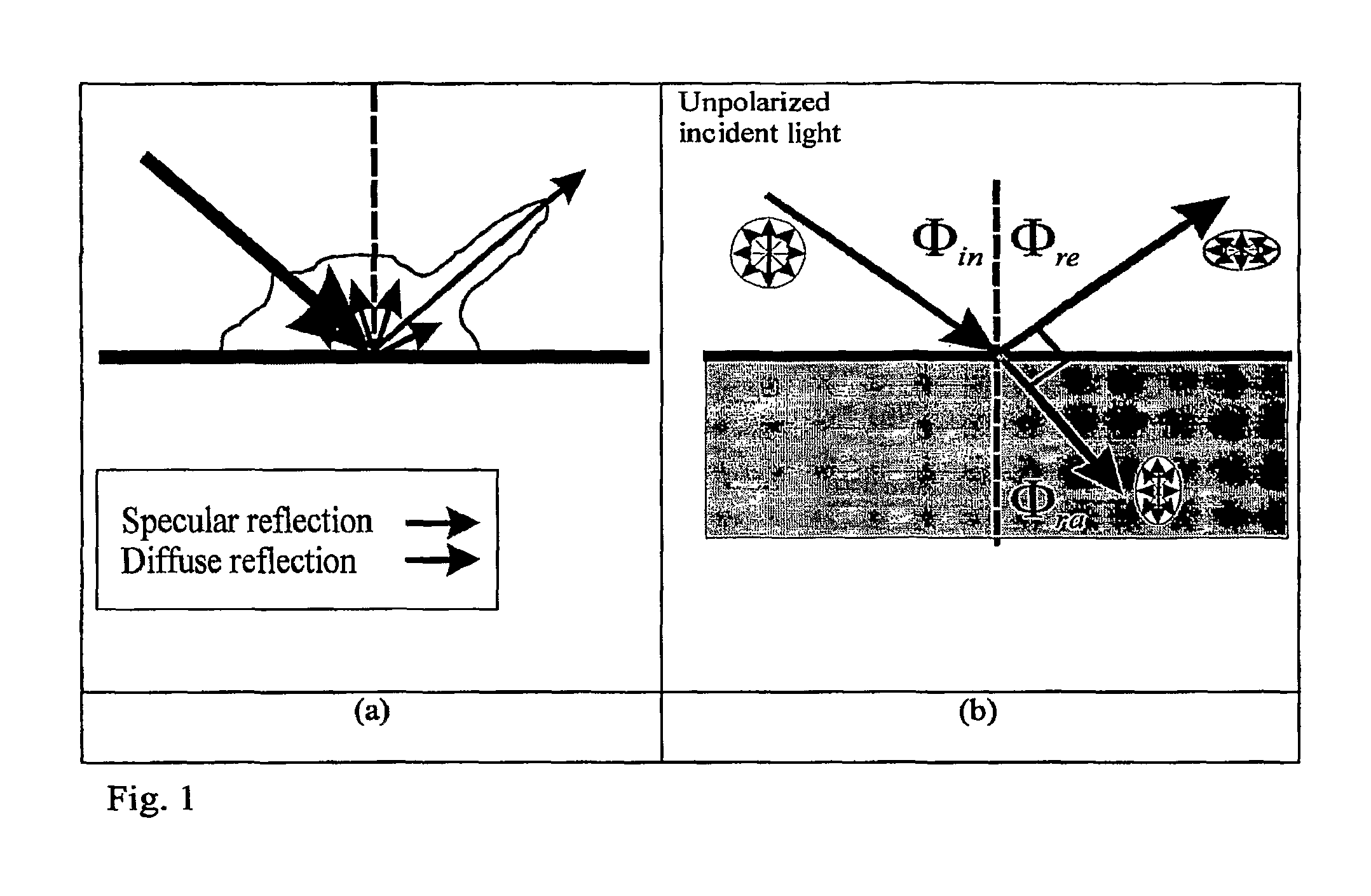
[0024]According to the generally accepted macroscopic description of the interaction of light with a surface, reflected light can be subdivided into specular and diffuse components. FIG. 1(a) illustrates the general macroscopic reflection model, while FIG. 1(b) illustrates the polarization of light resulting from specular reflection from a dielectric surface. The ratio of energy carried by the diffuse and specular components depends on the angle of incidence and the material properties of the surface. The diffusely reflected components often undergo multiple random reflections microscopically, so st...


PUM


Abstract

Shadow is an inseparable aspect of all natural scenes. When there are multiple light sources or multiple reflections several different shadows may overlap at the same location and create complicated patterns. Shadows are a potentially good source of information about a scene if the shadow regions can be properly identified and segmented. However, shadow region identification and segmentation is a difficult task and improperly identified shadows often interfere with machine vision tasks like object recognition and tracking. A shadow separation and contrast enhancement method based on the polarization of light is provided. Polarization information of scenes is captured by a polarization-sensitive camera and the scenes are processed to effectively separate shadows from different light sources.

Description

CROSS-REFERENCE TO RELATED APPLICATIONS[0001]This application is the National Stage of International Application No. PCT / US2007 / 016247 filed Jul. 17, 2007, which claims the benefit of U.S. Provisional Application No. 60 / 831,798, filed Jul. 18, 2006, and the entire disclosure of each application is incorporated by reference herein.FIELD OF THE INVENTION[0002]The present application relates to image processing and, more particularly, to techniques for separating and enhancing the contrast of overlapping cast shadow components within images and for detection and identification of objects hidden in shadows using polarization imaging by solving for the image intensity, degree of polarization, and polarization orientation angle of the resultant polarization images.BACKGROUND OF THE INVENTION[0003]Shadows are formed whenever an occlusion partially blocks the illumination of a surface or object by a light source. With the exception of the ambient light, which is assumed to be omni-direction...

Claims


Application Information

Patent Timeline
Patent Type & Authority Patents(United States)
IPC IPC(8): G06K9/40H04N5/202G06V10/145H04N23/76
CPCG06K9/2036G06T5/009G06K9/3241G06T5/50G06K2209/21G06V10/145G06V10/255G06V2201/07G06T5/92G06T5/00
Inventor PUGH, JR., EDWARD N.ENGHETA, NADERLIN, SHIH-SCHONYEMELYANOV, KONSTANTIN
Owner THE TRUSTEES OF THE UNIV OF PENNSYLVANIA
Learn More