
Machine to-machine communication system for payload control

a communication system and payload technology, applied in the field of machine to machine communication system, can solve the problems of affecting fuel economy, affecting the performance of the machine, increasing tire wear, etc., and achieve the effect of enhancing the payload of the haulage machine and enhancing the payload control

Active Publication Date: 2013-02-26
CATERPILLAR INC
View PDF30 Cites 16 Cited by
  • Summary
  • Abstract
  • Description
  • Claims
  • Application Information

AI Technical Summary

Benefits of technology

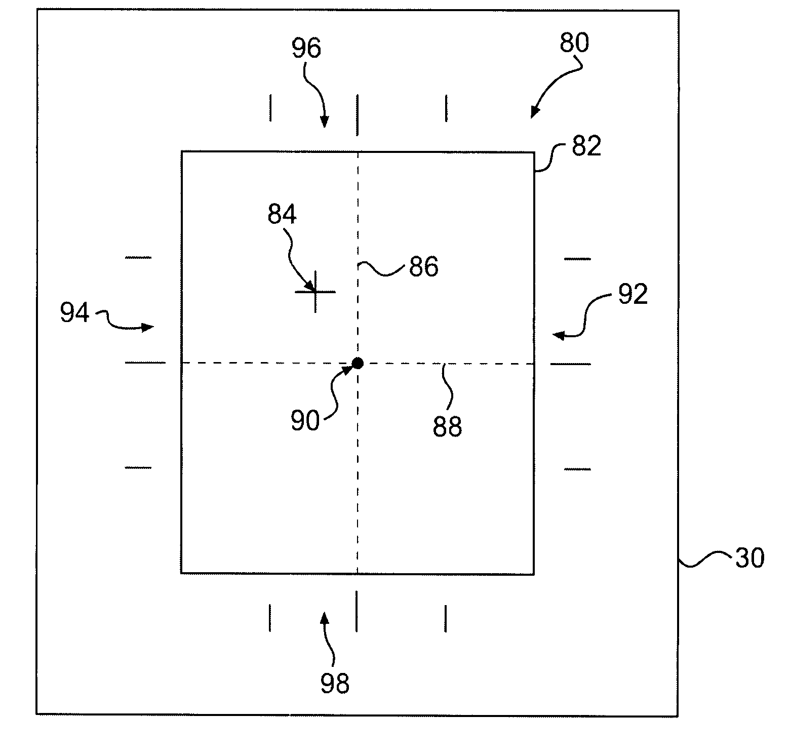
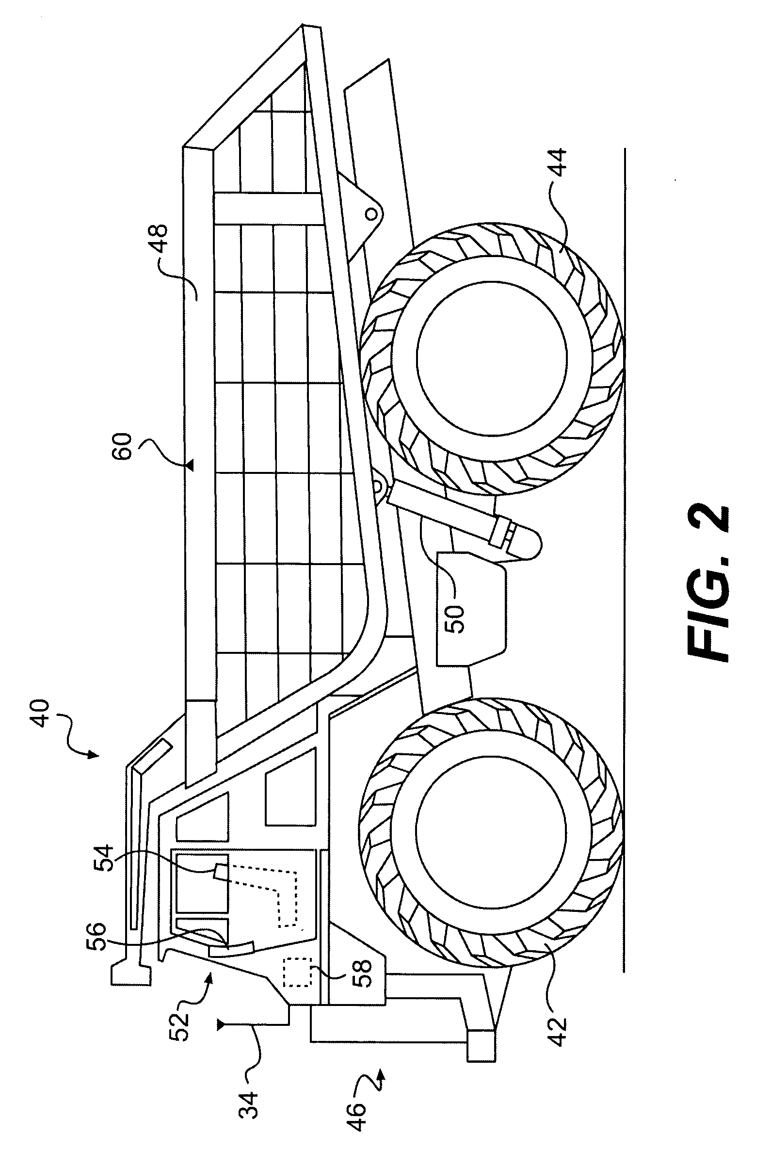
The present invention is about a system that helps increase the carrying capacity of a haulage machine used in construction or mining. This system includes a fleet of machines, including at least one haulage machine and at least one loading machine. The loading machine removes material from a supply and loads it into the haulage machine during work cycles. The system also includes a communication system between the haulage machine and the loading machine. Before the last work cycle, the haulage machine's controller determines the amount and distribution of payload within the machine. The loading machine's controller then receives a signal from the haulage machine indicating the amount and position of additional payload needed in the last work cycle. This system makes it easier to maximize the use of the haulage machine's capacity and reduces the likelihood of downtime or damage to equipment.

Problems solved by technology

A payload that is too heavy and / or not optimally balanced or distributed in an off-highway truck may increase tire wear, adversely affect fuel economy, and damage machine components.
In addition, machine design limits may be exceeded if an off-highway truck is extensively overloaded.
This may adversely affect braking and / or steering performance.
Even if machine components are not immediately damaged by a particular payload that may be excessive and / or unbalanced, the machine may be unduly stressed, and excessive component wear may result.
A payload that is not optimally distributed may result in poor ride control and operator stress.
In addition, a payload that is too light may decrease productivity.
While alluding to even distribution of material, the system of the '093 patent does not account for differing distribution characteristics among materials of different sizes.
Also, the system of the '093 patent does not communicate data to the loading machine so that it may know where to deposit a load, or how much material to deposit in a given load.
In addition, while mentioning filling the hauling machine to capacity, the system of the '093 patent does not account for situations where one more load from the loading machine may exceed the optimal capacity of the hauling machine.
As a result, material may not be evenly distributed and the hauling machine, in fact, may be overloaded.

Method used


Image

  • Machine to-machine communication system for payload control
  • Machine to-machine communication system for payload control
  • Machine to-machine communication system for payload control

Examples


Embodiment Construction

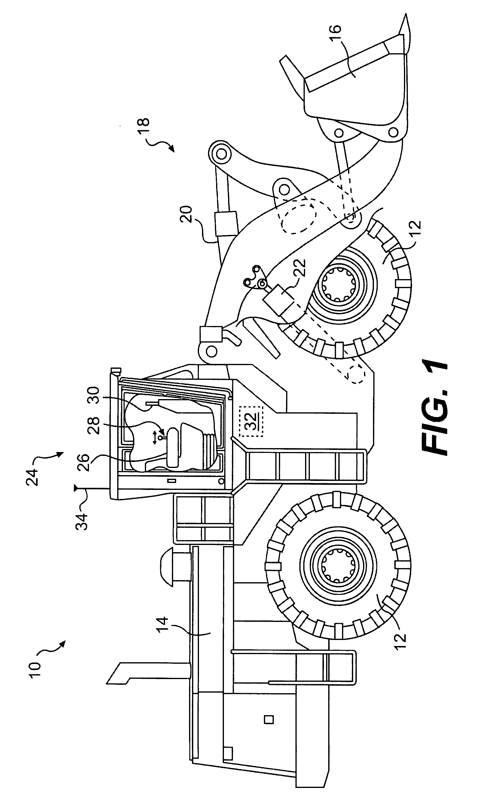
[0013]FIG. 1 diagrammatically illustrates one exemplary embodiment of a loading machine 10 which may be, for example, a wheel loader. Loading machine 10 may be propelled and transported on ground engaging devices 12, enabling the machine to function as a mobile unit. While ground engaging devices 12 are illustrated as wheels, it will be understood that loading machine 10 may be propelled and transported by other types of ground engaging devices, such as tracks. A suitable power source 14, e.g., a diesel engine, may be located on the loading machine 10 and may serve to drive one or more of the ground engaging devices and other components of loading machine 10.

[0014]A bucket 16 may be attached to loading machine 10 by suitable linkage 18, and may be manipulated via linkage 18 by suitable actuators 20, 22. It will be understood that the type and size of bucket 16 and the particular arrangement of linkage 18 may vary with the model and size of the loading machine 10. Loading machine 10,...


PUM


Abstract

A method for enhancing payload control is disclosed. The method includes removing material during a plurality of work cycles with at least one loading machine and associating the loading machine relative to at least one haulage machine. The method also includes determining the relative locations of the loading machine and the haulage machine and, during the plurality of work cycles, loading removed material into the haulage machine with the loading machine. The method also includes determining payload and payload distribution within the haulage machine at least before a last work cycle of the plurality of work cycles and communicating to the loading machine, via a machine-to-machine communication system, the amount and position within the haulage machine of additional payload desired in at least the last work cycle of the plurality of work cycles for desired payload and payload distribution.

Description

TECHNICAL FIELD[0001]The present disclosure is directed to a machine-to-machine communication system, and more particularly, a machine-to-machine communication system for payload control.BACKGROUND[0002]Machines may be used to move earth, rocks, and other materials from one location to another. It may be desirable to move material from an excavation site, for example, to another location sufficiently removed from the excavation site that the material must be transported some distance before being dumped. For example, the earth, rocks, and / or other materials may be loaded by one machine, such as a wheel loader, onto another machine, such as an off-highway truck, that may, in turn, transport the materials to a dump site.[0003]It may be important that the payload of the machine that transports the materials be within a certain load range, and that it be balanced within the payload carrier of the machine. A payload that is too heavy and / or not optimally balanced or distributed in an off...

Claims


Application Information

Patent Timeline
Patent Type & Authority Patents(United States)
IPC IPC(8): G06F19/00G01D21/00G06F17/10G05D5/00G01G19/08
CPCE02F9/2025G01G23/37G01G19/10E02F9/26E02F9/264
Inventor MOREY, STEPHEN J.VIK, TIMOTHY A.JOHNSTON, RICHARD D.ROTHWELL, JONATHAN W.
Owner CATERPILLAR INC
Learn More