
Cordless medical cauterization and cutting device

a cutting device and cauterization technology, applied in the field of medical cauterization and cutting devices, can solve the problems of not being able to rule out tissue necrosis, not being able to ensure tissue, and not being able to use prior art electrocautery devices, etc., to achieve accurate positioning of end effectors, increase firing forces, and high firing loads

Active Publication Date: 2013-02-19
COVIDIEN AG
View PDF120 Cites 679 Cited by
  • Summary
  • Abstract
  • Description
  • Claims
  • Application Information

AI Technical Summary

Benefits of technology

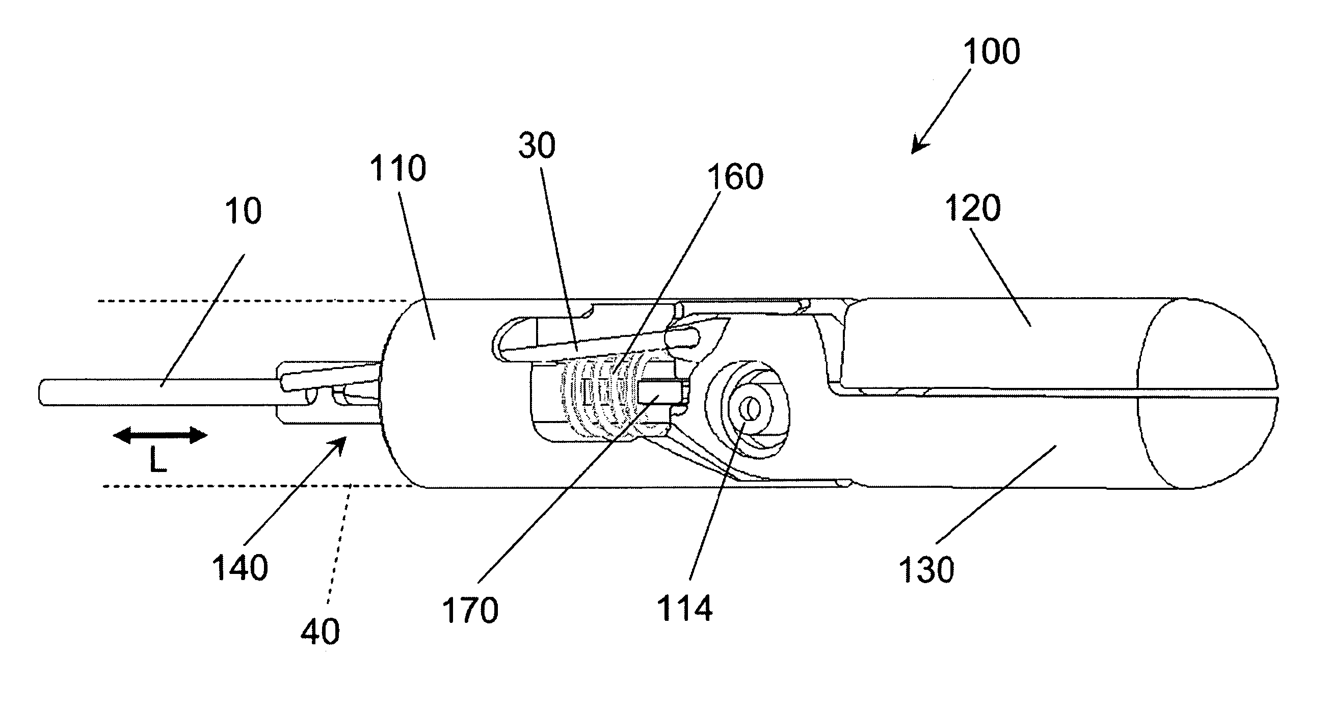
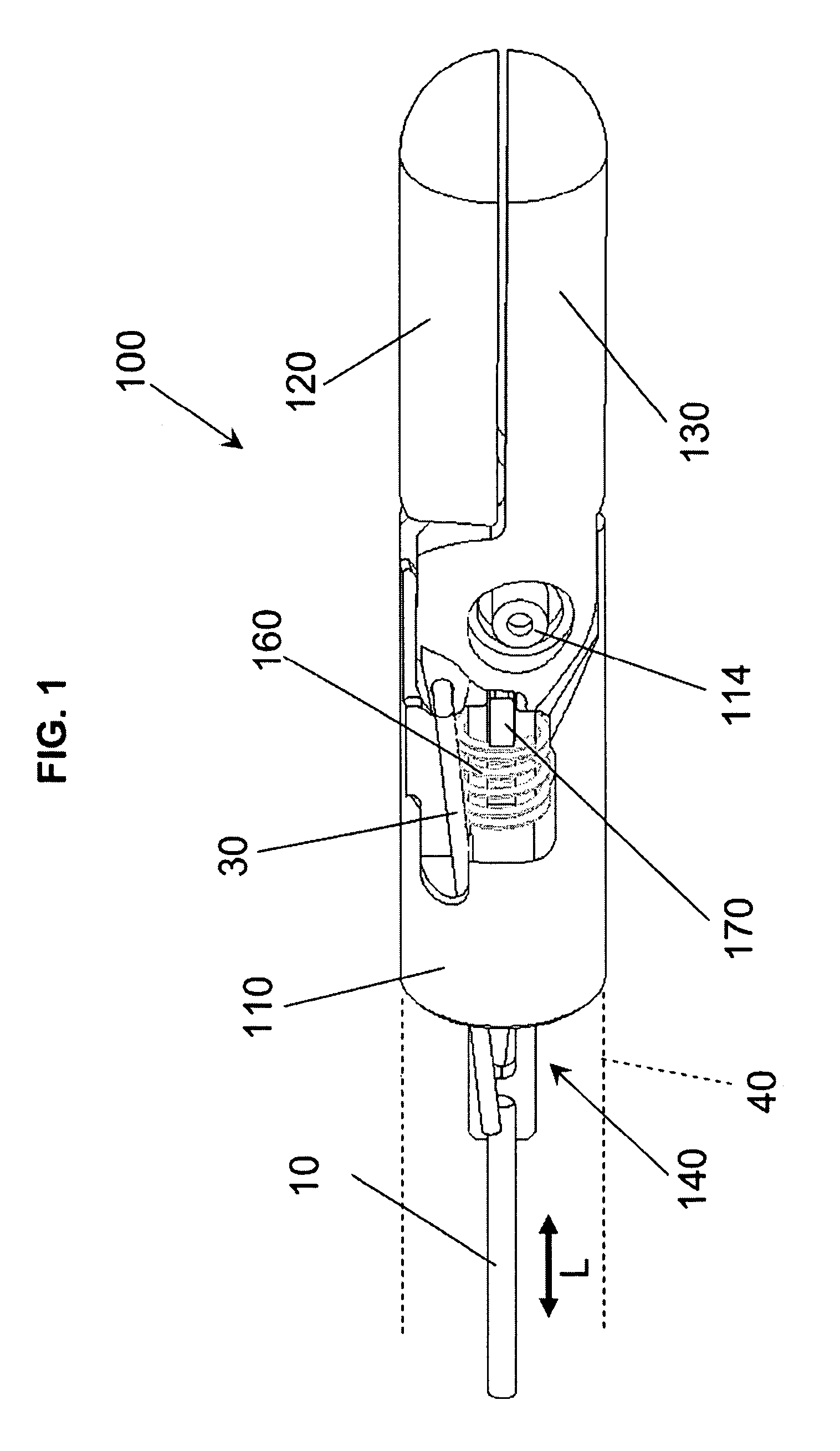
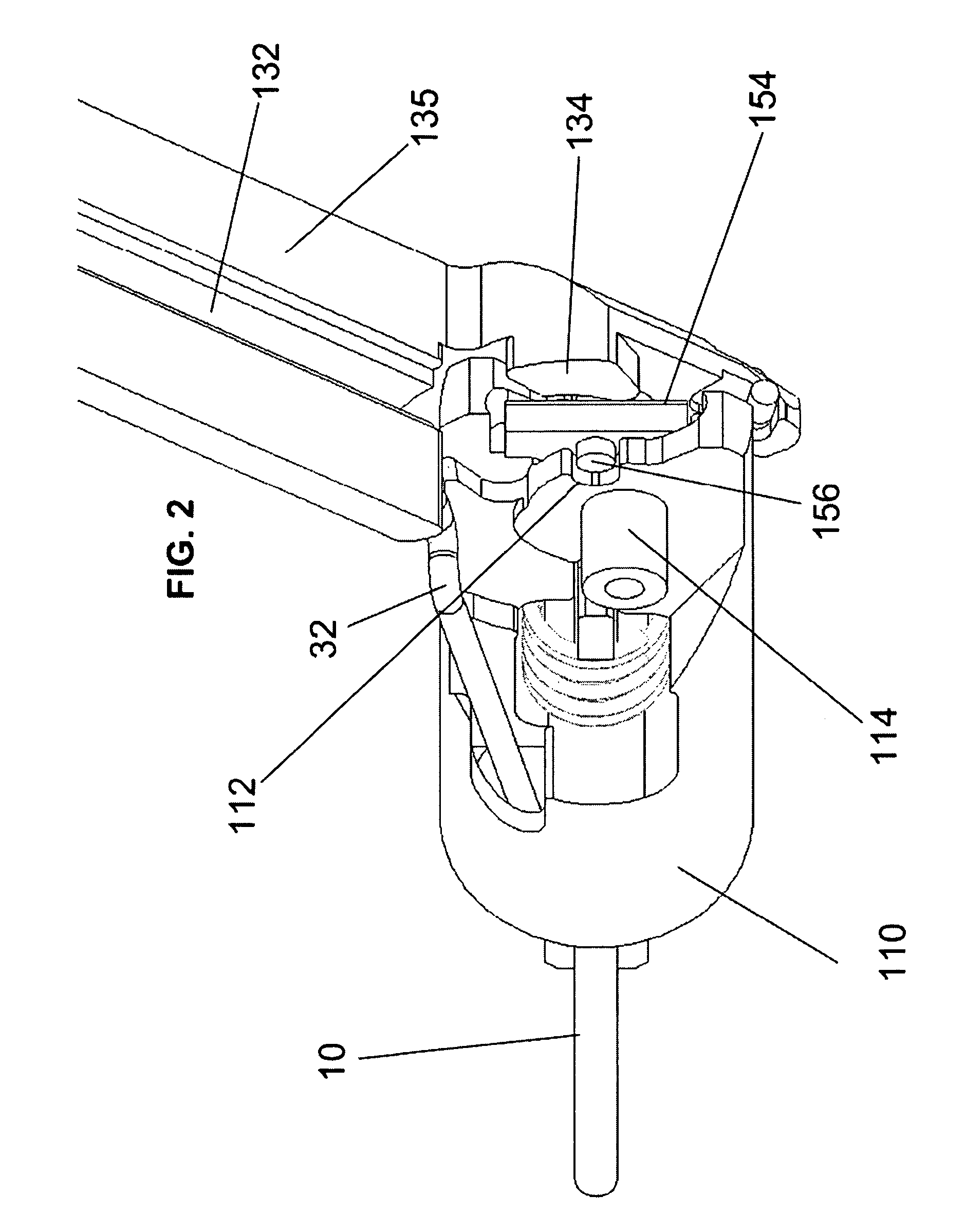
The present invention is a surgical instrument for endoscopic and laparoscopic procedures that allows the physician to use both hands independently. The instrument has a unique articulation mechanism that allows for easy and secure positioning of the end effector without the need for a second hand. The instrument also allows for dynamic rotation of the end effector, creating a compound angle for accurate positioning. The blade-firing mechanism is supported by support plates or a rigid channel to allow for high firing loads without excessive forces during articulation. The instrument can be manufactured in different lengths and is adapted for use with flexible endoscopes. It also includes a force switch to determine the optimal tissue compression range for safe and effective sealing and cutting. The instrument allows for optimal tissue compression based on the force supplied to the tissue between the jaws.

Problems solved by technology

Because there is no way to precisely control the exact kind of tissue that is being placed within the compressing jaws, it is not possible to ensure that the tissue is compressed within an Optimal Tissue Compression range, referred to as an OTC range.
Therefore, ruling out of tissue necrosis is difficult or not possible for prior art electrocautery devices.

Method used


Image

  • Cordless medical cauterization and cutting device
  • Cordless medical cauterization and cutting device
  • Cordless medical cauterization and cutting device

Examples


Embodiment Construction

[0136]Aspects of the invention are disclosed in the following description and related drawings directed to specific embodiments of the invention. Alternate embodiments may be devised without departing from the spirit or the scope of the invention. Additionally, well-known elements of exemplary embodiments of the invention will not be described in detail or will be omitted so as not to obscure the relevant details of the invention.

[0137]Before the present invention is disclosed and described, it is to be understood that the terminology used herein is for the purpose of describing particular embodiments only and is not intended to be limiting. It must be noted that, as used in the specification and the appended claims, the singular forms “a,”“an,” and “the” include plural references unless the context clearly dictates otherwise.

[0138]While the specification concludes with claims defining the features of the invention that are regarded as novel, it is believed that the invention will b...


PUM


Abstract

A cordless surgical device includes a modular battery, a radio-frequency signal generating assembly, a surgical handle and an interchangeable circuit casing. The RF signal generating assembly includes RF-signal-generating circuitry, a voltage-control circuit and an external output. The voltage circuit is configured to control an output of the RF-signal-generating circuitry. The handle is configured to support a bipolar end effector having jaws with bipolar contacts and a cutting blade disposed between the jaws. The handle includes leads operable to receive RF signals from the external output and defines an aseptically sealable battery-holding compartment configured to hold the battery. The circuit casing is configured to house the RF signal generating assembly and includes a securing connection adapted to couple the external output of the RF signal generating assembly to the leads. The external output is operable to impart RF signals to the handle when the circuit casing connects to the handle.

Description

CROSS-REFERENCE TO RELATED APPLICATIONS[0001]This application claims the priority, under 35 U.S.C. §119, of U.S. Provisional Patent Application Ser. Nos. 61 / 037,788 filed Mar. 19, 2008, and 61 / 101,005 filed Sep. 29, 2008, and is a continuation-in-part of U.S. patent application Ser. No. 12 / 270,111, filed Nov. 13, 2008, and is a divisional application of U.S. patent application Ser. No. 12 / 324,873, filed Nov. 27, 2008 (which CIP and divisional applications claim the priority, under 35 U.S.C. §119, of U.S. Provisional Patent Application Ser. Nos. 60 / 990,784 filed Nov. 28, 2007, 61 / 030,748 filed Feb. 22, 2008), the entire disclosures of which are all hereby incorporated herein by reference in their entireties.STATEMENT REGARDING FEDERALLY SPONSORED RESEARCH OR DEVELOPMENT[0002]n / aFIELD OF THE INVENTION[0003]The present invention lies in the field of medical cauterization and cutting devices. The present disclosure relates to a cordless electrosurgical forceps for sealing and / or cutting...

Claims


Application Information

Patent Timeline
Patent Type & Authority Patents(United States)
IPC IPC(8): A61B18/18
CPCA61B18/1445A61B2017/00734A61B2018/00404A61B2018/00601A61B2018/1226A61B2018/1412A61B2018/1455A61B2018/1861
Inventor DEVILLE, DEREK DEEPALMER, MATTHEW A.BALES, THOMAS O.KLINE, KOREYMCBRAYER, SEAN
Owner COVIDIEN AG
Learn More