Pivot bearing

a bearing and pivoting technology, applied in the direction of knife-edge bearings, machines/engines, positive displacement liquid engines, etc., can solve the problems of high level of wear of the support journal, fast wear of the cage and the spring element, and the difficulty of arranging the support journal on the cage, etc., to prevent the effect of slipping and small expenditur

Inactive Publication Date: 2013-02-19
SCHAEFFLER TECH AG & CO KG
View PDF4 Cites 9 Cited by
  • Summary
  • Abstract
  • Description
  • Claims
  • Application Information

AI Technical Summary

Benefits of technology

[0009]It is the object of the present invention, proceeding from DE 34 42 391 C1, to provide a pivot bearing whose cage is prevented from slipping in the pivot bearing with little expenditure, and which does not have an increased spatial requirement for this purpose.

Problems solved by technology

This necessitates a support journal on the cage, though the arrangement of said support journal on the cage is difficult.
The restoring forces which act on the support journal lead to fast wear of the cage and of the spring element.
A high level of wear to the support journal occurs in said solution too.
Said solution also requires a spring element which is subject to a high level of wear.
The form-fitting action is obtained in that the rolling bodies and the two bearing surfaces are provided with a toothing, which however has the result that the production of the pivot bearing is very complex.
A disadvantage of said solution is that the guide device must be arranged on the outer sides of the segment rolling bearing, resulting in an increased spatial requirement.

Method used


Image

  • Pivot bearing
  • Pivot bearing
  • Pivot bearing

Examples


Embodiment Construction

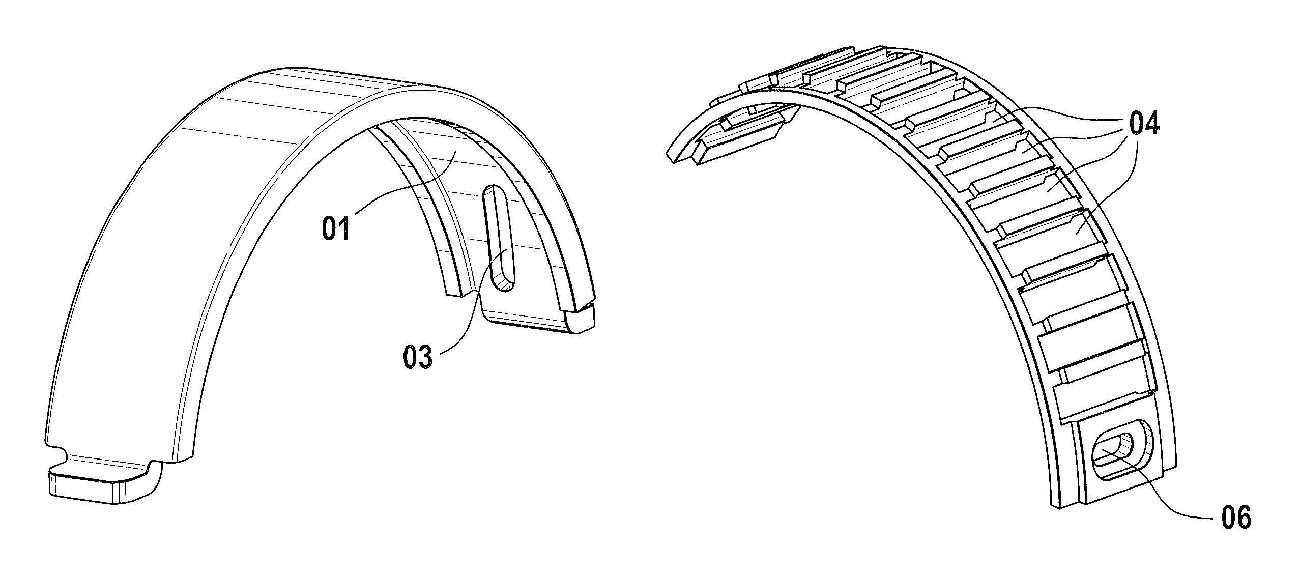
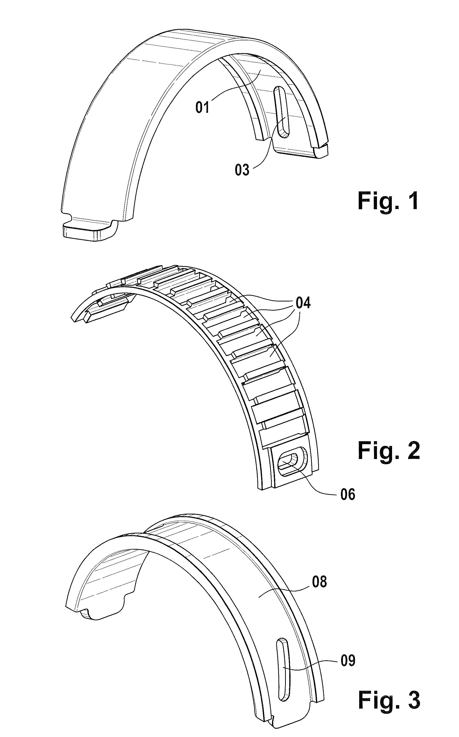
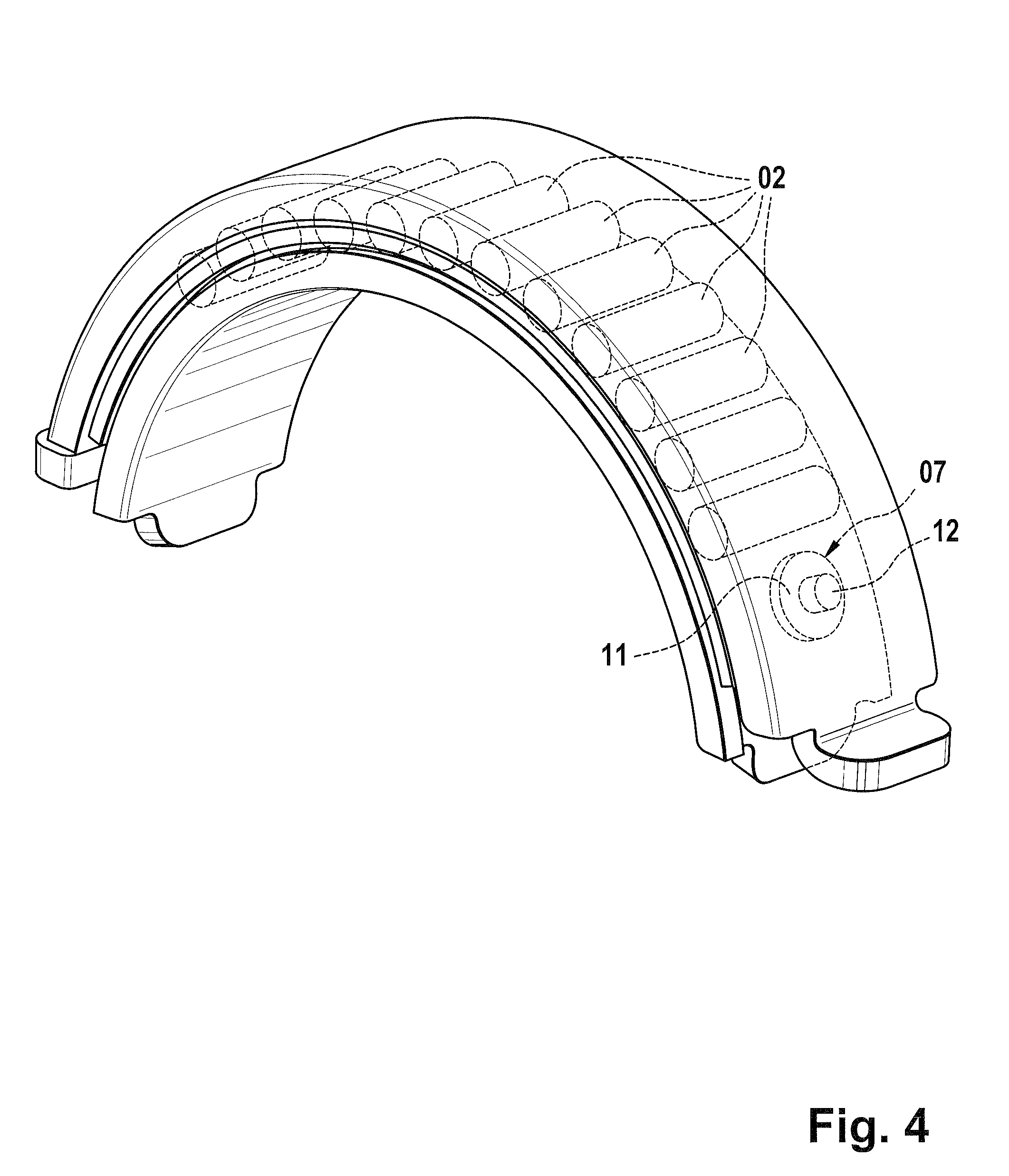
[0029]FIG. 1 shows an outer ring segment of a pivot bearing according to the invention in a perspective view. The outer ring segment extends over an arc of almost 180°, such that said outer ring segment is of approximately semi-circular design. A first bearing surface 01 is formed on the inner side of the outer ring segment, on which first bearing surface 01 rolling bodies in the form of rollers 02 (shown in FIG. 4) can roll in the conventional way. The first bearing surface 01 has the shape of a segment of a hollow cylinder, as a result of which a counterpart, which is cylindrical at least in sections, can rotate in the first bearing surface 01.

[0030]The first bearing surface 01 has a first groove 03 which is inclined with respect to a running direction of the rolling bodies 02. The angle of inclination of the first groove 03 with respect to the running direction of the rolling bodies 02 is approximately 30°. The first groove 03 is arranged in a region of the first bearing surface ...


PUM


Abstract

A pivot bearing having a first bearing surface of hollow cylindrical design, at least in sections. Guided in the first bearing surface is a second bearing surface of hollow cylindrical design, at least in sections. Rolling bodies are arranged between the bearing surfaces. The pivot bearing also has a cage for guiding the rolling bodies, and a slide block to prevent the cage from slipping. A first grove is formed in the first bearing surface and a second grove is formed in the second bearing surface. The groves are inclined transversely with respect to the running direction of the rolling bodies. The opposite inclination of the groves has the result that, if the spacing between the bearing surfaces is neglected, the grooves intersect. The sliding block is guided between the grooves. The cage has a recess that holds the sliding block permitting cage control.

Description

[0001]This application claims the priority of DE 10 2007 060 470.1 filed Dec. 14, 2007, and is incorporated by reference herein.FIELD OF THE INVENTION[0002]The present invention relates to a pivot bearing, such as is used for example as a swashplate pivot bearing in hydraulic axial piston engines.BACKGROUND OF THE INVENTION[0003]Pivot bearings are usually designed as segment rolling bearings in which it is necessary to take special precautions to ensure that the rolling bearings and a cage which guides the latter do not slide out of the pivot bearing.[0004]DE 26 25 298 A1 presents a guide device for a cage of a segment rolling bearing. Said guide device has a spring element which, in the event of a deviation of the cage from its intended position, exerts a restoring force on the cage. This necessitates a support journal on the cage, though the arrangement of said support journal on the cage is difficult. The restoring forces which act on the support journal lead to fast wear of the ...

Claims


Application Information

Patent Timeline
Patent Type & Authority Patents(United States)
IPC IPC(8): F16C33/46
CPCF04B1/2085F04B1/324F16C19/502F16C33/306F16C33/4623F16C2360/42F16C2360/00
Inventor BECKER, KLAUSWINKLER, THOMASVORNEHM, HARALDGEORGI, JANGOERWITZ, THOMASPETER, ALEXANDER
Owner SCHAEFFLER TECH AG & CO KG
Why Eureka
Try Eureka