
Artificial ear and method for detecting the direction of a sound source using the same

a technology of artificial ear and direction, applied in the direction of transducer details, electrical transducers, signal processing, etc., can solve the problems of reduced estimation resolution, inability to discriminate front-back, and confusion of front-back

Active Publication Date: 2013-02-05
KOREA INST OF SCI & TECH
View PDF32 Cites 0 Cited by
  • Summary
  • Abstract
  • Description
  • Claims
  • Application Information

AI Technical Summary

Benefits of technology

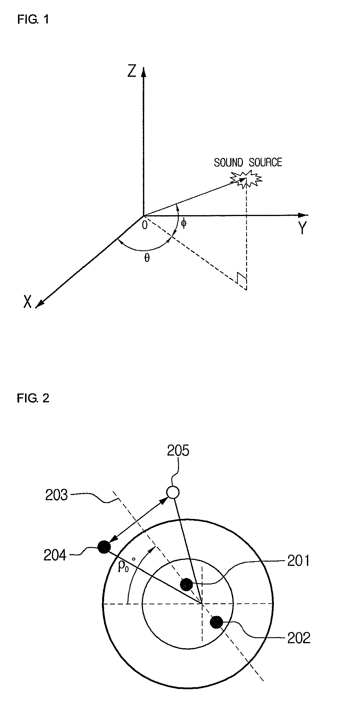
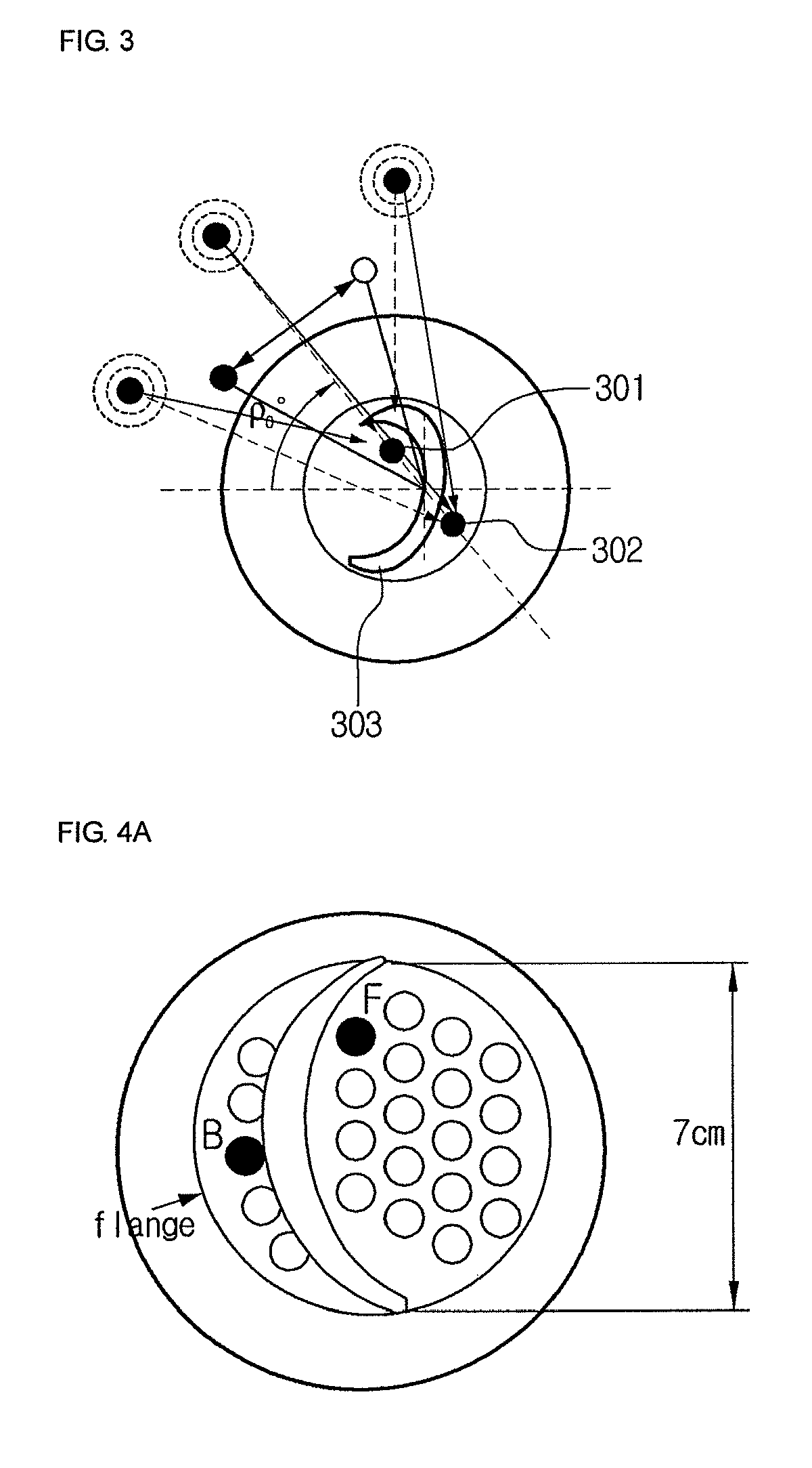
[0011]Disclosed herein are an artificial ear in which a difference between output signals respectively inputted to a plurality of microphones, generated by one or more structures disposed between the plurality of microphones so that front-back confusion can be prevented and the direction of a sound source can be detected in real time. Therefore, the artificial ear to various robot platforms using the localization method for detecting the direction of a sound source using the artificial ear can be applied.

Problems solved by technology

However, when there is a constraint that a microphone should be disposed in a narrow area such as the position of each person's ear, i.e., when the distance between the microphones is shortened, the method is disadvantageous in that estimation resolution is reduced.
When only two microphones are used in a narrow area, a sound source has the same delay time at two positions on a two-dimensional plane, and therefore, front-back confusion occurs.
That is, if the position of a sound source is estimated based on only the delay time difference when only the two microphones are used, front-back discrimination is impossible.
Therefore, the method is disadvantageous in that a relatively large-sized artificial ear is needed and the amount of database for sound source direction detection is increased.
Therefore, the beam-forming method is disadvantageous in that it is unsuitable for detecting the direction of a sound source in real time.
When the arrangement of microphones is restricted due to the shape of a robot platform, there is a limitation in applying the related art techniques.

Method used


Image

  • Artificial ear and method for detecting the direction of a sound source using the same
  • Artificial ear and method for detecting the direction of a sound source using the same
  • Artificial ear and method for detecting the direction of a sound source using the same

Examples


Embodiment Construction

[0024]Exemplary embodiments now will be described more fully hereinafter with reference to the accompanying drawings, in which exemplary embodiments are shown. This disclosure may, however, be embodied in many different forms and should not be construed as limited to the exemplary embodiments set forth therein. Rather, these exemplary embodiments are provided so that this disclosure will be thorough and complete, and will fully convey the scope of this disclosure to those skilled in the art. In the description, details of well-known features and techniques may be omitted to avoid unnecessarily obscuring the presented embodiments.

[0025]The terminology used herein is for the purpose of describing particular embodiments only and is not intended to be limiting of this disclosure. As used herein, the singular forms “a”, “an” and “the” are intended to include the plural forms as well, unless the context clearly indicates otherwise. Furthermore, the use of the terms a, an, etc. does not de...


PUM


Abstract

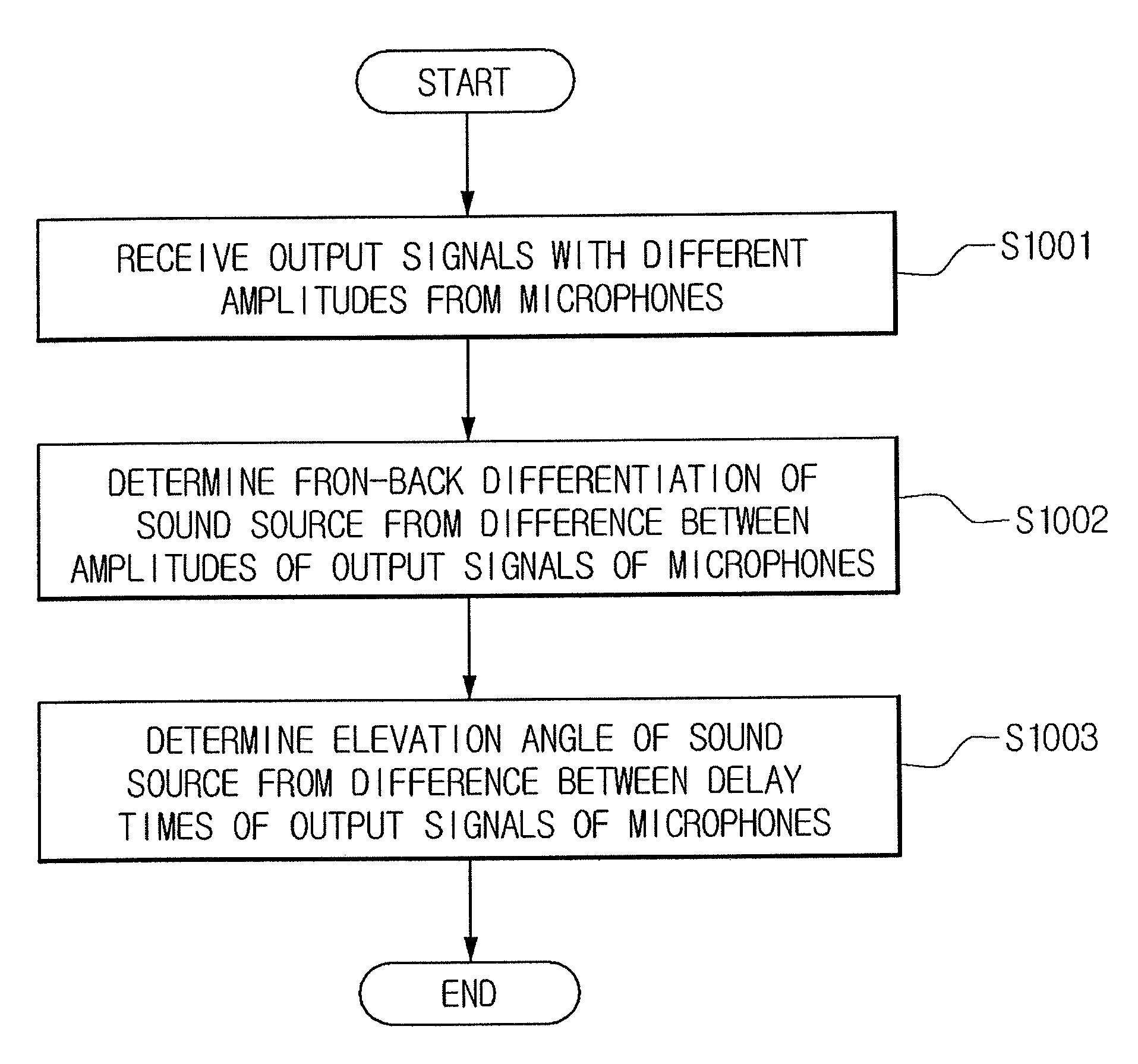
Disclosed herein are an artificial ear and a method for detecting the direction of a sound source using the same. The artificial ear includes a plurality of microphones; and one or more structures disposed between the plurality of microphones. In the artificial ear, the amplitudes of output signals respectively inputted to the plurality of microphones are designed to be different based on the direction of a sound source. The method for detecting the direction of a sound source includes receiving output signals with different amplitudes from a plurality of microphones; determining front-back discrimination of the sound source from a difference between the amplitudes of the output signals of the microphones; and determining an angle corresponding to the position of the sound source from a difference between delay times of the output signals of the microphones.

Description

CROSS-REFERENCE TO RELATED APPLICATION[0001]This application claims priority from and the benefit of Korean Patent Application No. 10-2009-116695, filed on Nov. 30, 2009, which is hereby incorporated by reference for all purposes as if fully set forth herein.BACKGROUND[0002]1. Field of the Invention[0003]Disclosed herein are an artificial ear and a method for detecting the direction of a sound source using the same.[0004]2. Description of the Related Art[0005]Recently, much interest has been focused on industries for intelligent robots that can interact with human beings. It is important that a robot detect the exact position of a robot user who is a conversational partner for Human-Robot Interaction (HRI). Therefore, a technique for detecting the direction of a sound source using an acoustic sensor is one of essential techniques for HRI.[0006]The related art technique for detecting the direction of a sound source includes a method using Time Delay Of Arrivals (TDOA), a method using...

Claims


Application Information

Patent Timeline
Patent Type & Authority Patents(United States)
IPC IPC(8): H04R25/00
CPCH04R3/005H04R1/406H04S2400/11H04S2420/01H04R2430/21
Inventor CHOI, JONGSUKPARK, YOUNGINLEE, SANGMOON
Owner KOREA INST OF SCI & TECH
Learn More